21 Concepts
14 Concepts
11 Concepts
11 Concepts
16 Concepts
8 Concepts
18 Concepts
12 Concepts
6 Concepts
12 Concepts
6 Concepts
5 Concepts
6 Concepts
9 Concepts
8 Concepts
8 Concepts
7 Concepts
9 Concepts
10 Concepts
8 Concepts
13 Concepts
5 Concepts
11 Concepts
10 Concepts
7 Concepts
6 Concepts
9 Concepts
10 Concepts
6 Concepts
9 Concepts

Fluid dynamics governs the motion of fluids through pipes, channels, and open systems using fundamental principles like Bernoulli's equation and conservation of mass. This JoVE Coach course explores practical applications in U.S. infrastructure including water distribution networks, dam spillways, sewage treatment systems, and hydraulic structures. Students learn to analyze pressure variations, velocity changes, and energy transformations in real-world fluid systems.
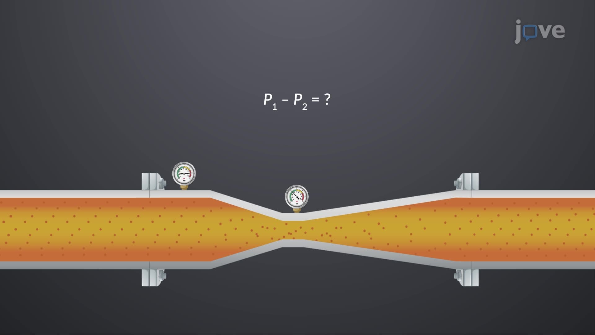
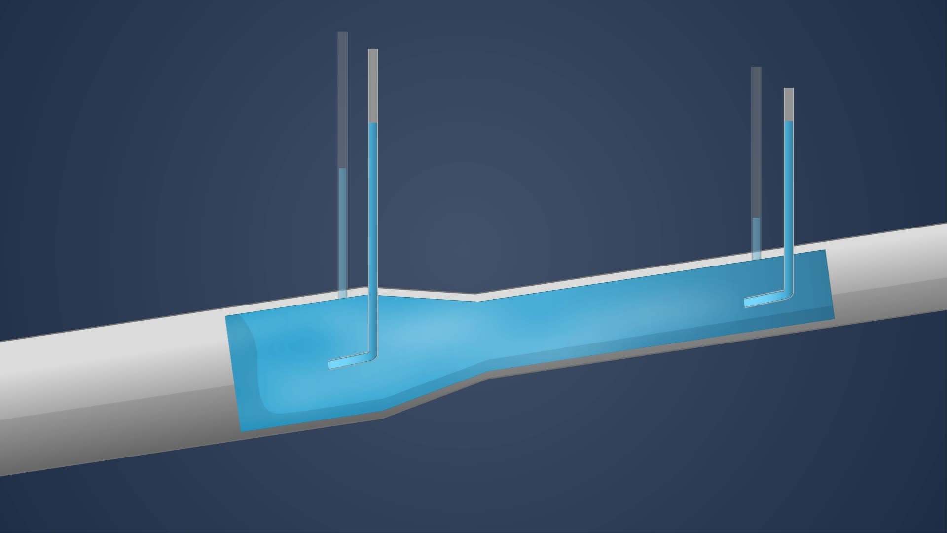
1. Bernoulli's Equation Along Streamlines: This fundamental principle relates pressure, velocity, and elevation in flowing fluids, assuming steady, incompressible flow without friction. The equation demonstrates energy conservation as fluid moves through varying pipe diameters or elevation changes. In U.S. water distribution systems, engineers use this principle to predict pressure drops in municipal networks, ensuring adequate water pressure reaches high-rise buildings in cities like New York and Chicago. The relationship shows that as water velocity increases through narrower pipe sections, pressure decreases proportionally, making it essential for designing efficient pumping systems.
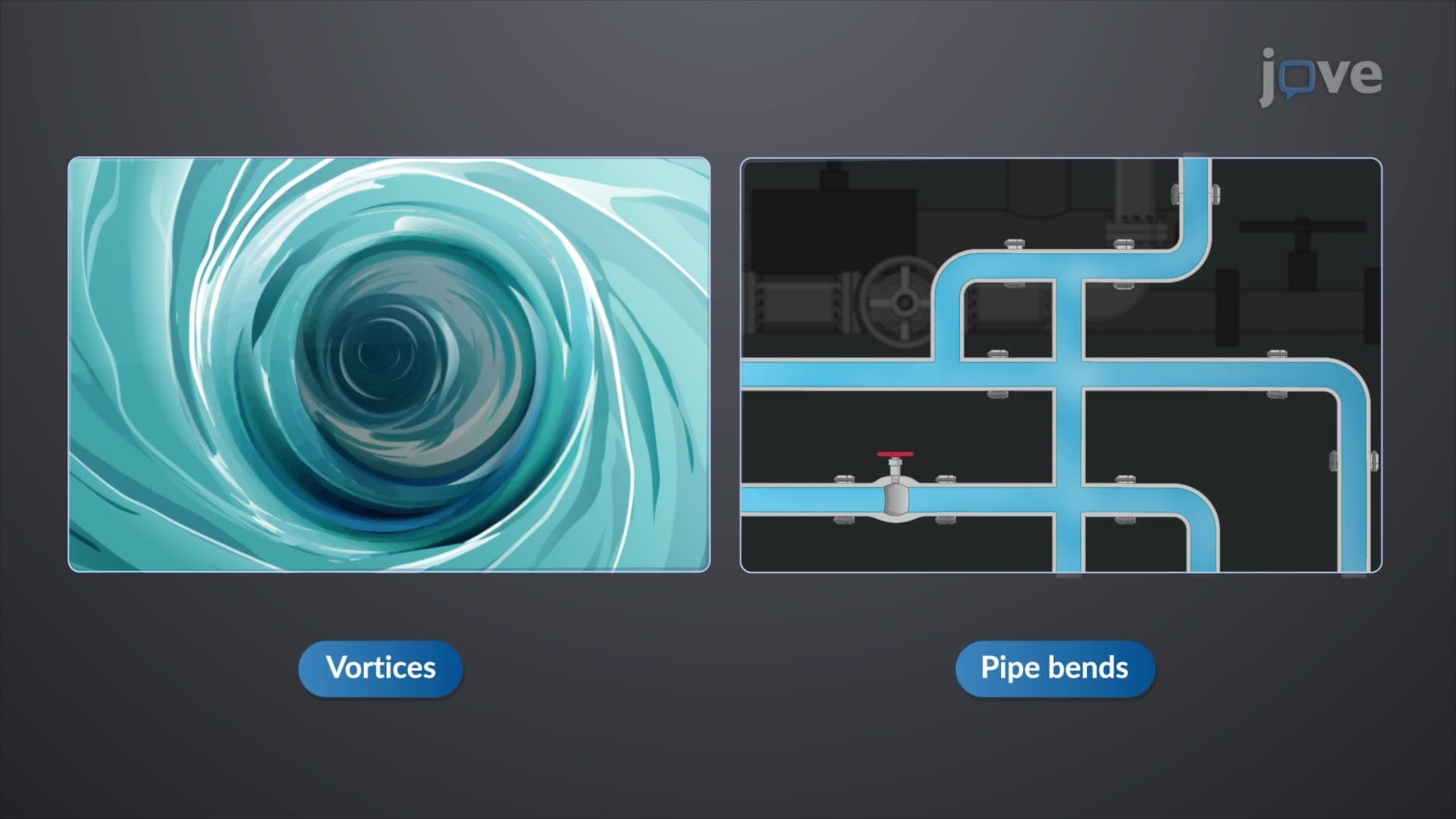
2. Pressure Variations in Curved Flow: When fluid flows along curved streamlines, centrifugal forces create pressure differences across the flow path. Higher pressure occurs on the inner curve radius, while lower pressure develops on the outer edge. This concept is crucial for designing curved highway drainage systems, river channel modifications, and pipeline bends in U.S. infrastructure projects. Engineers must account for these pressure variations when designing the curved spillways at dams like Hoover Dam, where water flows along sharply curved surfaces at high velocities, requiring careful structural analysis to prevent failure.
3. Continuity Equation and Flow Conservation: The continuity equation expresses conservation of mass in fluid systems, stating that mass flow rate remains constant in a steady flow system. This principle explains why water accelerates when flowing from larger to smaller pipe diameters, as seen in Venturi meters used throughout U.S. sewage treatment facilities. For incompressible fluids like water, the equation simplifies to show that area and velocity are inversely proportional. Municipal water engineers apply this concept when designing pipe networks for cities, ensuring adequate flow rates through varying pipe sizes from treatment plants to residential areas.
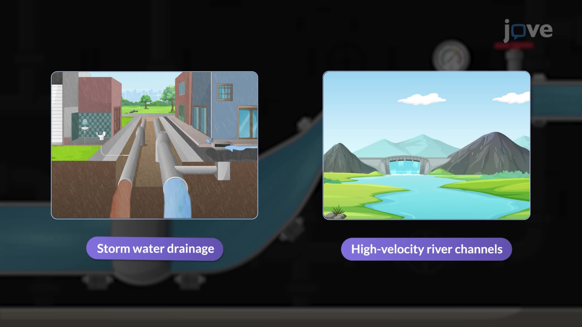
4. Static, Dynamic, and Stagnation Pressure: Total pressure in fluid systems consists of three components that help engineers analyze energy distribution. Static pressure acts perpendicular to surfaces and depends on fluid height and density, crucial for calculating forces on dam walls like those at Glen Canyon Dam. Dynamic pressure relates to fluid velocity and represents kinetic energy, important in high-speed applications such as stormwater drainage systems during flash floods in southwestern U.S. cities. Stagnation pressure occurs where fluid velocity reduces to zero, measured at dam faces and turbine blades in hydroelectric facilities throughout the Pacific Northwest.
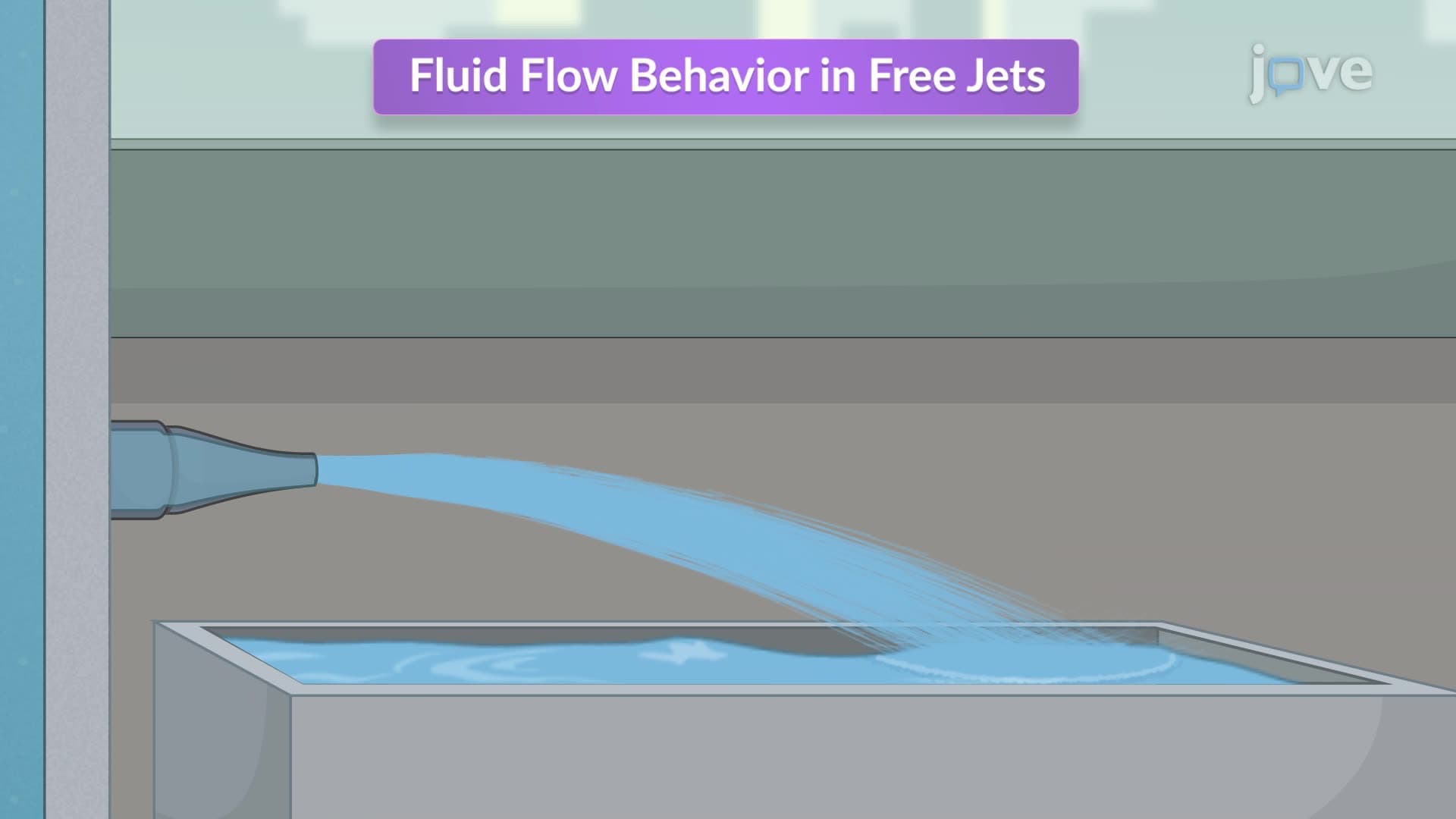
5. Free Jets and Vena Contracta: Free jets demonstrate how fluid exits nozzles and flows into open air, converting potential energy to kinetic energy. The phenomenon creates the vena contracta, where the jet narrows just outside the nozzle opening due to fluid inertia. Different nozzle designs affect the contraction coefficient, influencing flow patterns in spillway systems at U.S. dams. Engineers designing fountain systems in public spaces, agricultural irrigation sprinklers in California's Central Valley, and fire suppression systems must understand this behavior to predict actual flow rates and optimize nozzle performance for specific applications.
6. Energy and Hydraulic Gradient Lines: These graphical representations help visualize energy distribution in pipeline systems, with the energy line showing total energy and the hydraulic gradient line representing pressure plus elevation energy. The difference between these lines equals velocity head, always making the energy line higher during flow conditions. Understanding these concepts prevents cavitation problems in water supply systems and helps design siphon systems used in water treatment plants across the United States. Engineers monitoring the Trans-Alaska Pipeline use these principles to detect leaks, prevent water hammer effects, and ensure adequate pressure throughout the system's 800-mile length.