Loading video…


 8 Concepts
 10K views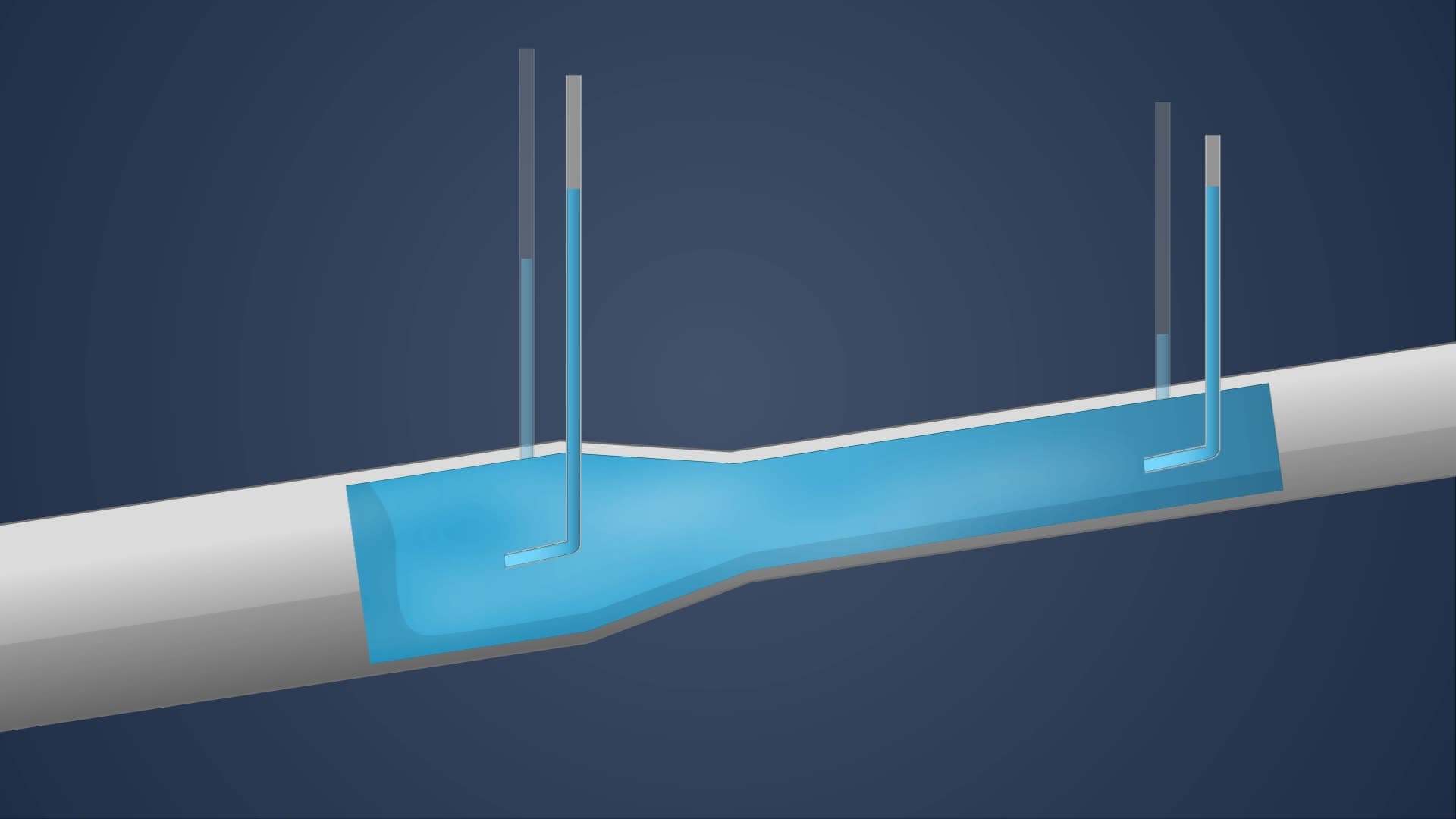

Video Summary: Energy Line and Hydraulic Gradient Line Explained
Ever wonder how engineers ensure water slides at Six Flags deliver thrilling rides without structural failure? The secret lies in understanding energy line and hydraulic gradient line concepts. These fundamental hydraulic principles determine how water flows through any piped system, from massive theme park attractions to municipal water supplies. The energy line represents total fluid energy (pressure + velocity + elevation), while the hydraulic gradient line shows only pressure and elevation components. Watch the full video on JoVE Coach to master this concept with expert-led visuals and step-by-step explanations.
The energy line and hydraulic gradient line serve as essential visualization tools in fluid mechanics, helping engineers analyze and design hydraulic systems from residential plumbing to complex industrial processes. These concepts form the backbone of hydraulic analysis taught in AP Physics, college-level fluid mechanics courses, and professional engineering examinations.
The energy line represents Bernoulli's equation in graphical form, incorporating three distinct energy components. Pressure head reflects the fluid's internal pressure energy, elevation head accounts for gravitational potential energy, and velocity head represents kinetic energy from fluid motion. For water flowing through a pipe, total energy = (pressure/specific weight) + elevation + (velocity²/2g). This relationship appears frequently on MCAT physics sections and college fluid mechanics exams, requiring students to manipulate each component independently.
The hydraulic gradient line excludes velocity head, showing only pressure and elevation energy components. This distinction proves crucial in practical applications like designing water treatment plants in cities such as Denver, Colorado, where elevation changes significantly impact system pressure. When the hydraulic gradient line drops below pipe elevation, negative pressure conditions develop, potentially causing cavitation damage to pumps and pipe systems. Understanding this relationship helps engineering students solve complex problems on the Fundamentals of Engineering (FE) exam.
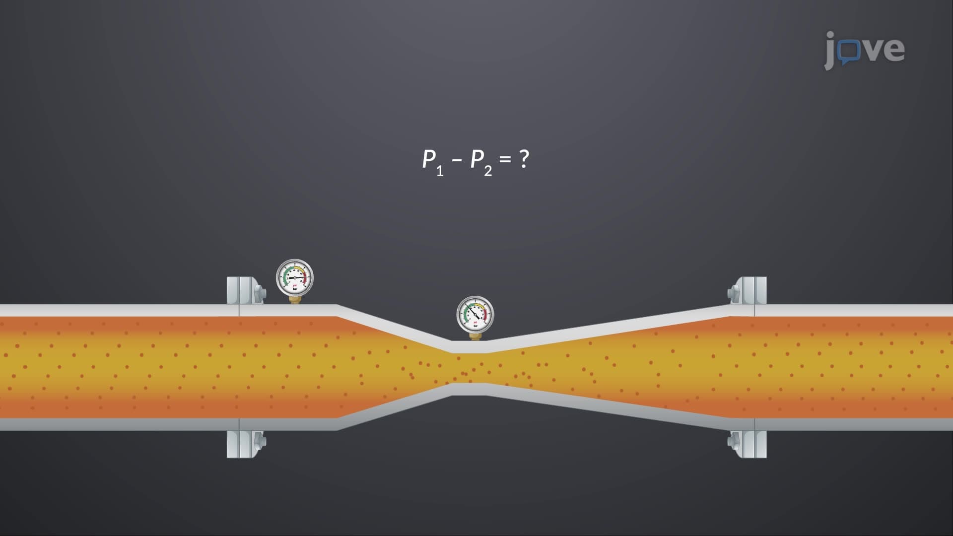
Engineers use specialized instruments to measure these energy lines in operating systems. Piezometers measure static pressure at specific points, while Pitot tubes capture total pressure including velocity effects. Major infrastructure projects, such as the California State Water Project, rely on these measurements to optimize pump station operations and prevent costly system failures. Students studying for AP Environmental Science or civil engineering courses must understand how these measurements inform decisions about pipeline routing, pump sizing, and surge protection systems.
Related Micro-courses