Loading subject page…


21 Concepts
14 Concepts
11 Concepts
11 Concepts
16 Concepts
8 Concepts
18 Concepts
12 Concepts
6 Concepts
12 Concepts
6 Concepts
5 Concepts
6 Concepts
9 Concepts
8 Concepts
8 Concepts
7 Concepts
9 Concepts
10 Concepts
8 Concepts
13 Concepts
5 Concepts
11 Concepts
10 Concepts
7 Concepts
6 Concepts
9 Concepts
10 Concepts
6 Concepts
9 Concepts
 9 Concepts
 9.8K Views
 Popular topics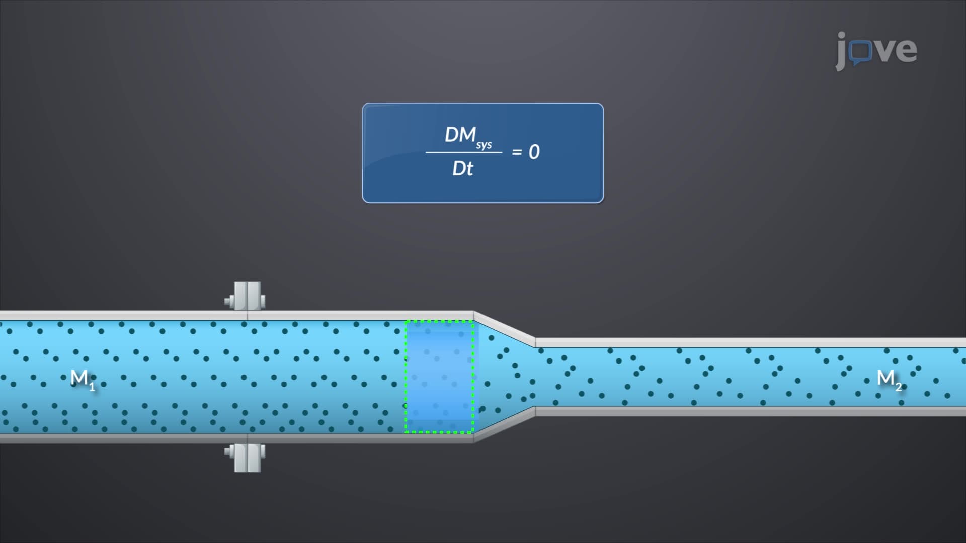




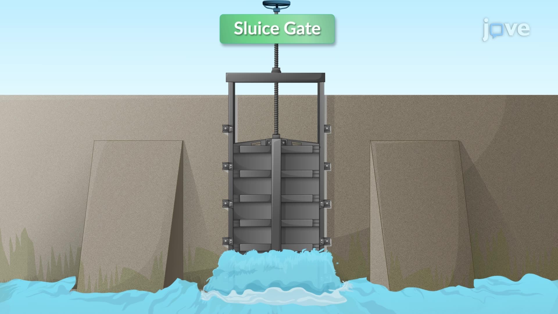
Finite control volume analysis provides engineers with a systematic approach to study fluid flow by examining mass, momentum, and energy conservation within defined boundaries. This fundamental methodology, supported by the Reynolds transport theorem, enables analysis of complex fluid systems from hydraulic engineering in US water treatment facilities to aerospace applications in aircraft design. JoVE Coach guides students through practical applications including sewer systems, wind turbines, and sluice gates.
1. Conservation of Mass and Continuity Equation: The principle that mass cannot be created or destroyed within a fluid system forms the foundation of control volume analysis. In steady flow conditions, the mass flow rate entering a control volume equals the mass flow rate exiting, regardless of changes in cross-sectional area or velocity. This concept applies directly to US municipal water systems where engineers design pipe networks to maintain consistent flow rates through varying pipe diameters, ensuring adequate water pressure throughout residential neighborhoods and commercial districts.
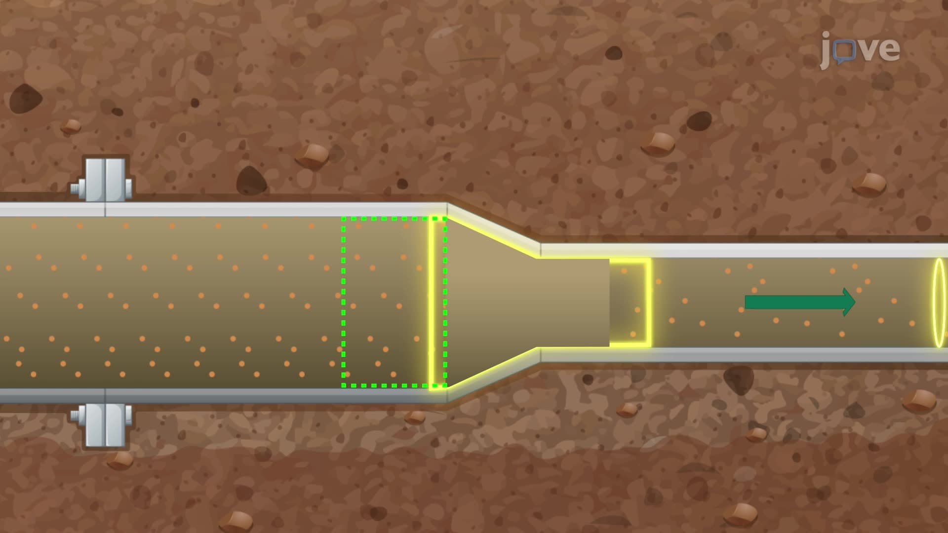
2. Reynolds Transport Theorem and Control Volume Approach: This mathematical framework transforms conservation laws from following individual fluid particles to analyzing fixed regions in space. The theorem relates the time rate of change of any extensive property within a system to corresponding changes within a control volume plus the net flux of that property across control surfaces. American aerospace engineers use this approach when designing aircraft fuel systems, where fuel must flow consistently through tanks and lines despite changes in aircraft orientation and acceleration during flight maneuvers.
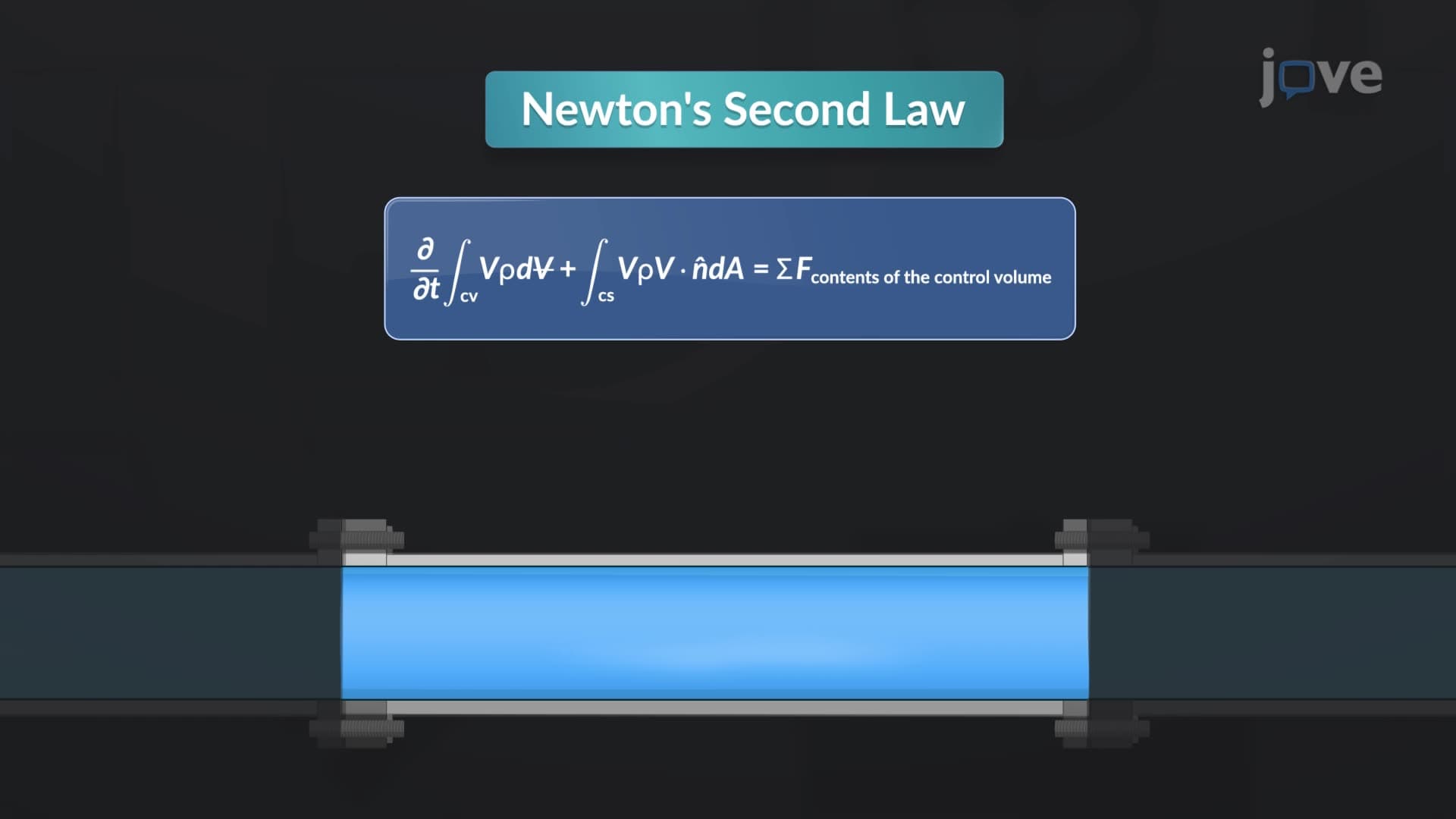
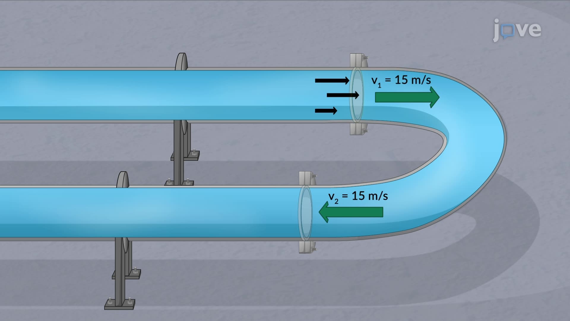
3. Linear Momentum Conservation in Fluid Systems: Newton's second law applied to fluid flow states that the net force on a control volume equals the rate of momentum change plus the net momentum flux across boundaries. This principle governs the analysis of forces in pipe systems, such as the anchoring forces required for U-shaped pipe bends in industrial facilities. US petroleum refineries rely on these calculations to design secure piping systems that can withstand the momentum changes as crude oil flows through complex processing equipment at high velocities and pressures.
4. Moment-of-Momentum Equation for Rotating Systems: Angular momentum conservation describes torque generation in rotating fluid machinery, where the net torque equals the rate of angular momentum change within the control volume plus net angular momentum flux. This equation is essential for analyzing wind turbines across American wind farms, where engineers must calculate the torque produced by air flowing over rotating blades to optimize power generation and ensure structural integrity during varying wind conditions throughout different seasons.
5. Energy Conservation and the First Law of Thermodynamics: The energy equation for control volumes states that the rate of energy change equals net heat addition plus net work input, including shaft work and flow work. This principle governs pump and turbine analysis in US hydroelectric facilities, where engineers calculate power requirements to lift water through different elevations while accounting for energy losses due to friction. The equation helps determine pump specifications for municipal water treatment plants that must deliver consistent water pressure to communities at various elevations.
6. Practical Applications in Hydraulic Engineering: Control volume analysis enables engineers to design and analyze hydraulic structures like sluice gates, weirs, and spillways common in US flood control systems. The methodology determines forces acting on these structures, flow rates through openings, and water levels upstream and downstream. The US Army Corps of Engineers applies these principles when designing flood control systems along major rivers like the Mississippi, ensuring structures can withstand hydrostatic forces while controlling water flow during flood events and normal operations.