Loading subject page…

- Mechanical Engineering
- Torsion
- Stress Concentrations in Circular Shafts
Micro-course: Torsion
5,181 views
Learn key concepts and earn your certificate.

Stress Concentrations in Circular Shafts

00:00
01:18
Video Summary: Stress Concentration Effects in Circular Shafts
Ever wondered why airplane propeller shafts don't snap under massive rotational forces? Stress concentration effects in circular shafts create dangerous weak points where applied torques and diameter changes cause stress to spike far beyond normal predictions. Boeing's turbine shafts experience this phenomenon when gear couplings and keyways disrupt the smooth stress flow that engineers calculate using standard torsion formulas. These concentrated stresses can cause catastrophic failures if not properly managed through design modifications like fillets and stress concentration factors. Watch the full video on JoVE Coach to master this concept with expert-led visuals and step-by-step explanations.
- Understand how stress concentration effects in circular shafts deviate from uniform torsion theory predictions
- Identify key sources of stress concentration including keyways, gear couplings, and abrupt diameter changes
- Analyze the role of stress concentration factors in quantifying maximum stress values at critical points
- Apply fillet radius calculations to reduce dangerous stress concentrations in shaft design
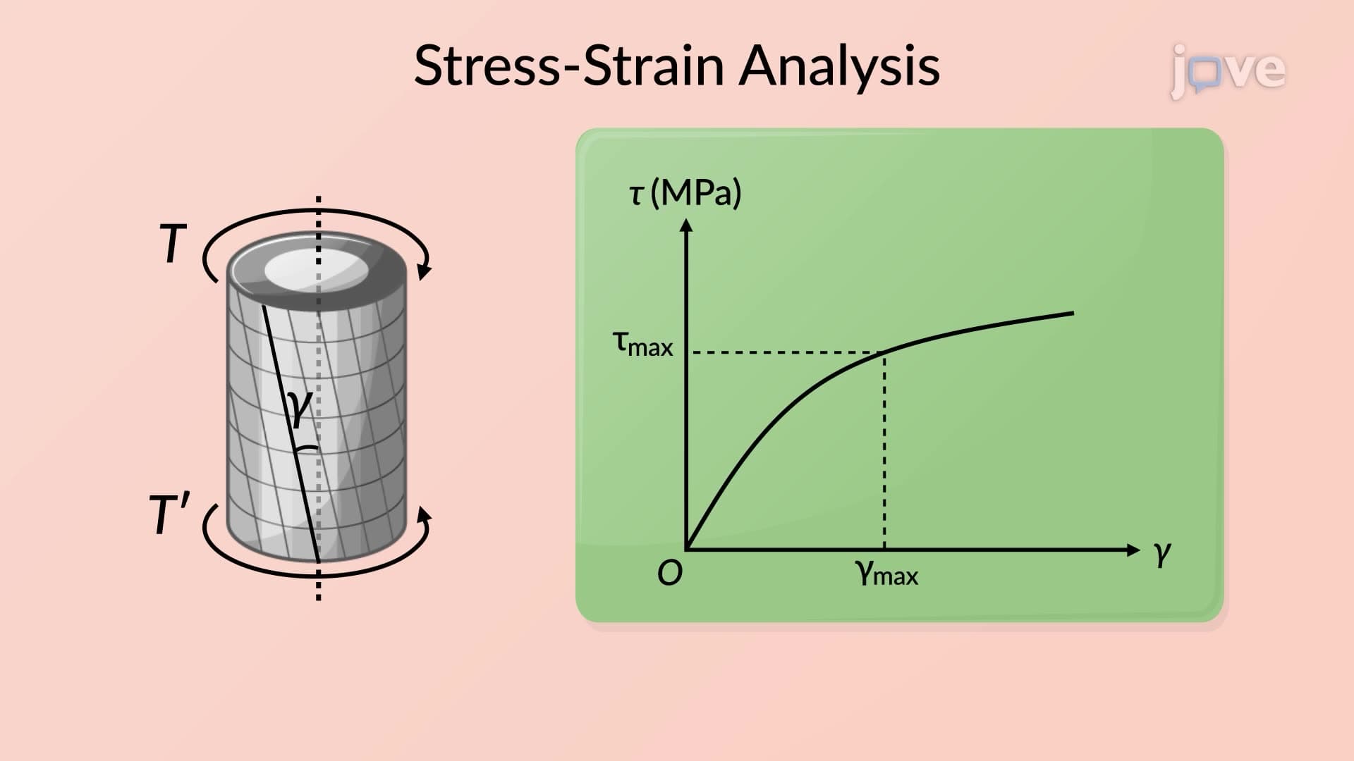
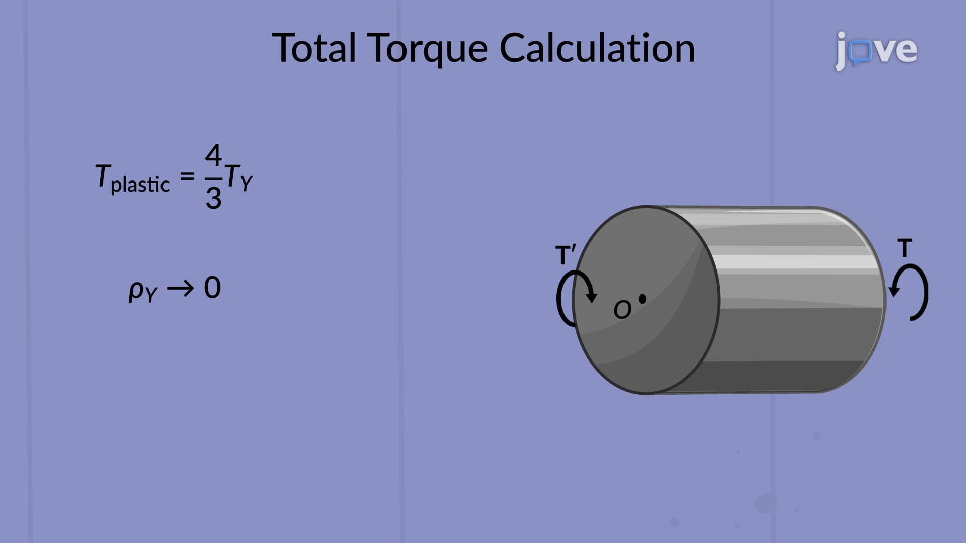
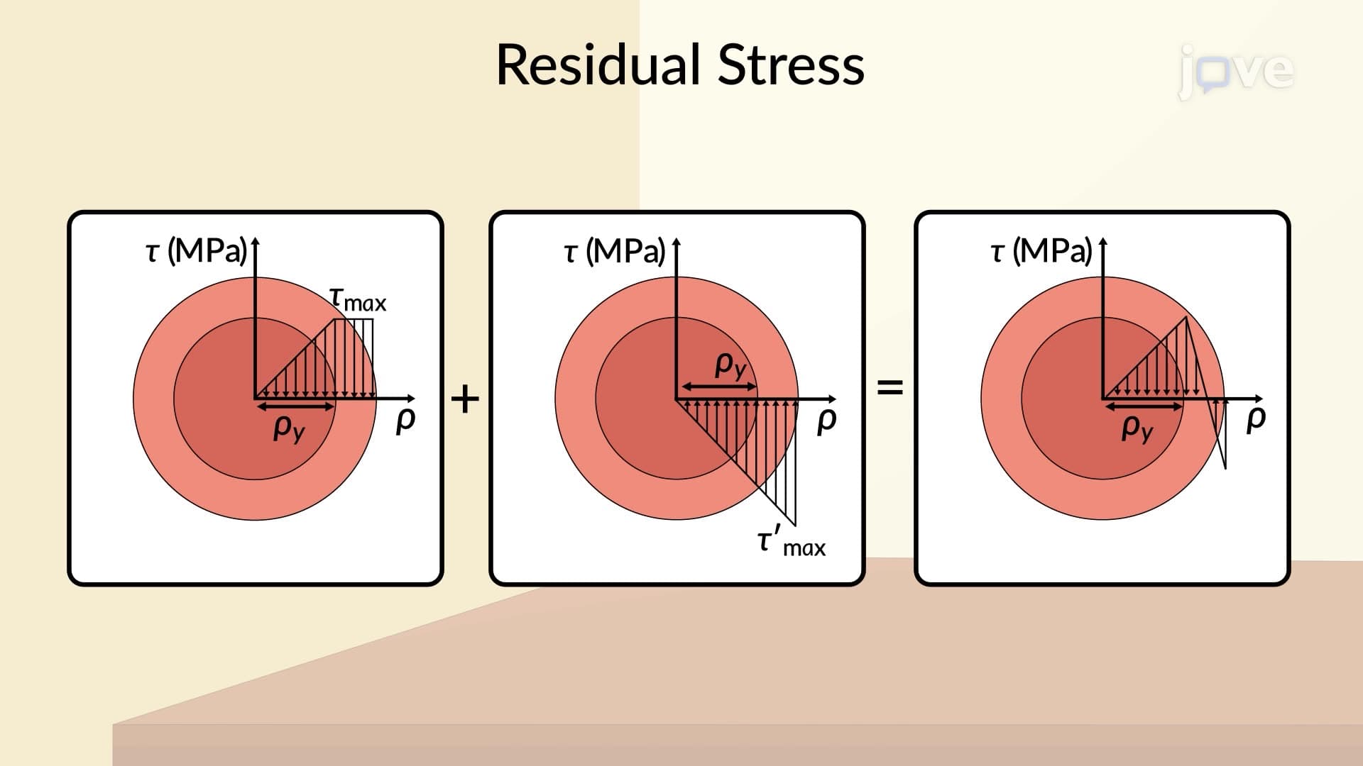
- Evaluate when elastic torsion formulas remain valid versus when plastic deformation occurs
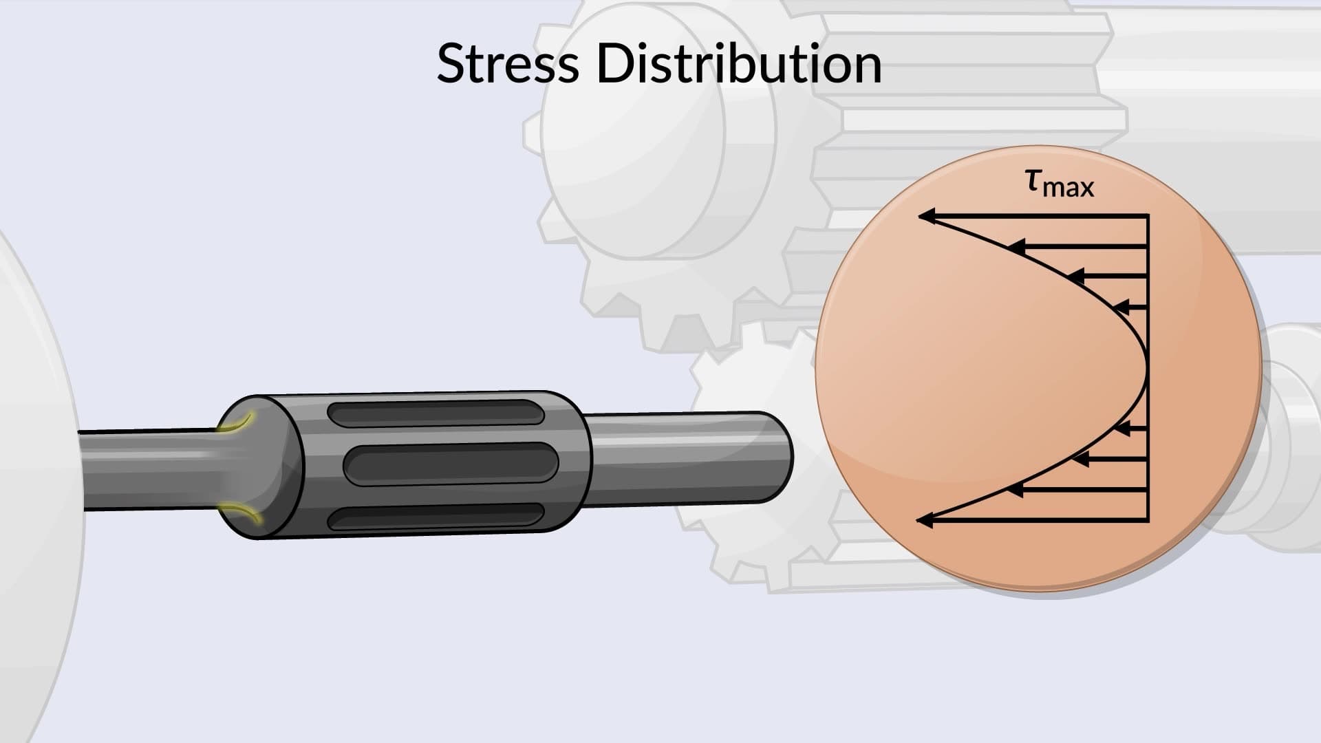
- Compare stress distributions in uniform shafts versus shafts with geometric discontinuities
- Recognize practical torque application methods that create non-uniform stress patterns
- Explore design strategies for minimizing stress concentration effects in real engineering applications
Understanding Stress Concentration Effects in Circular Shafts
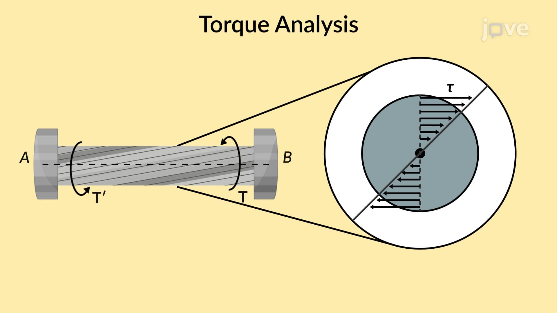
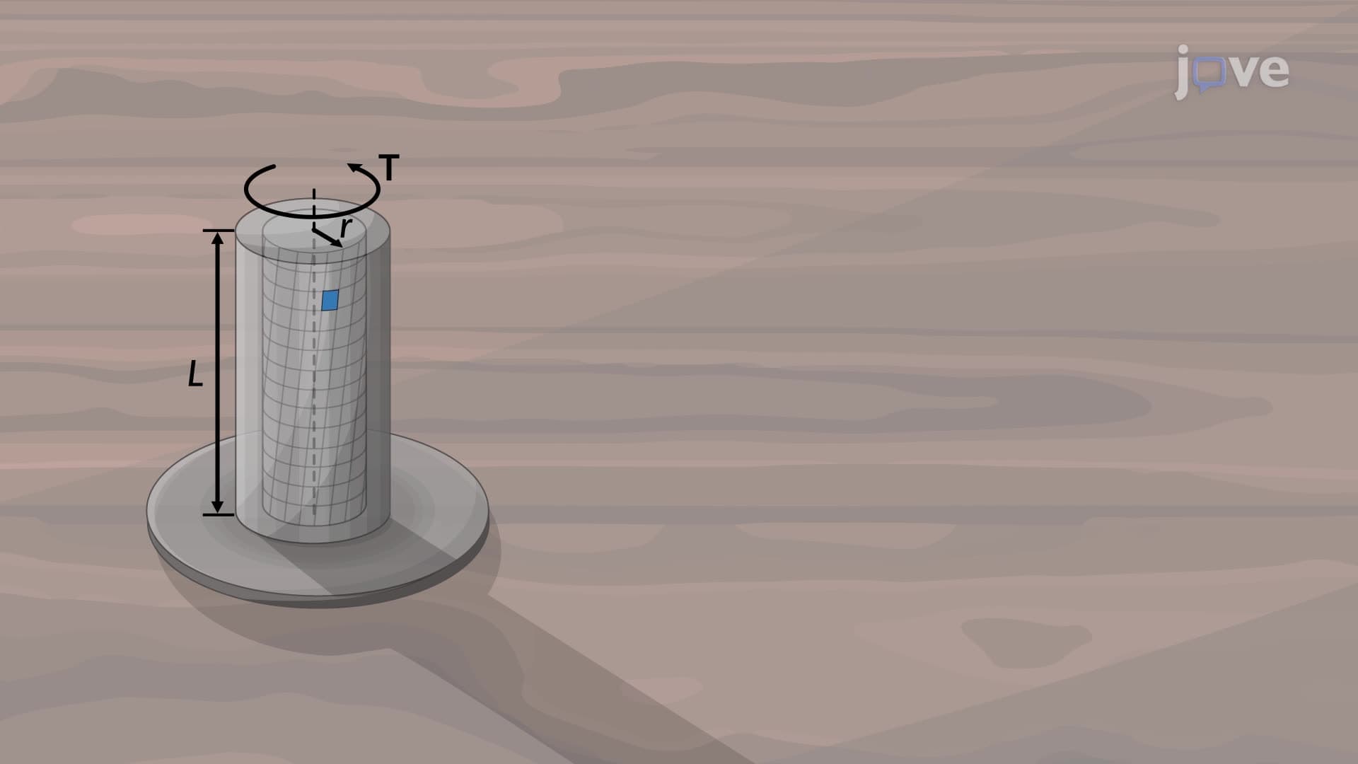
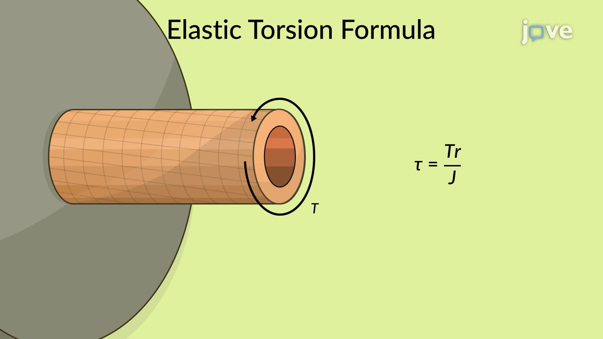
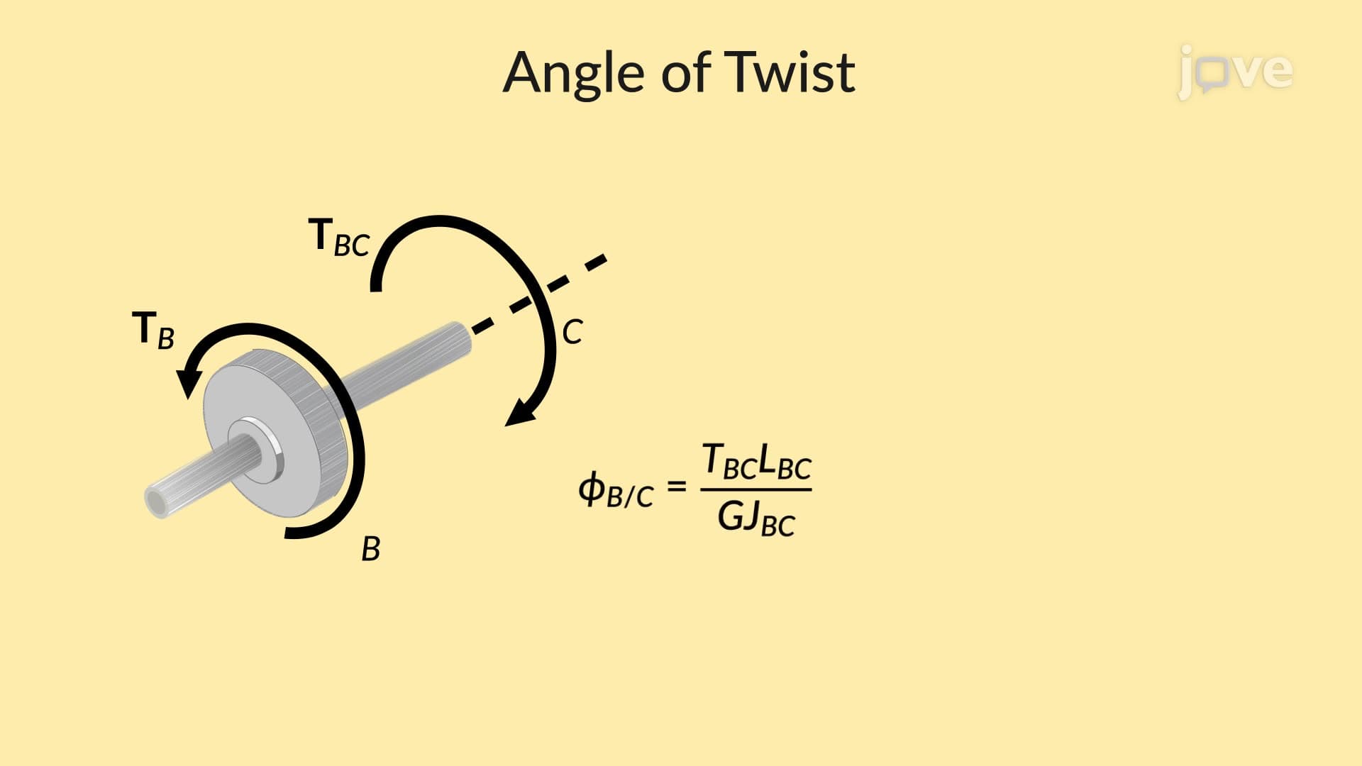
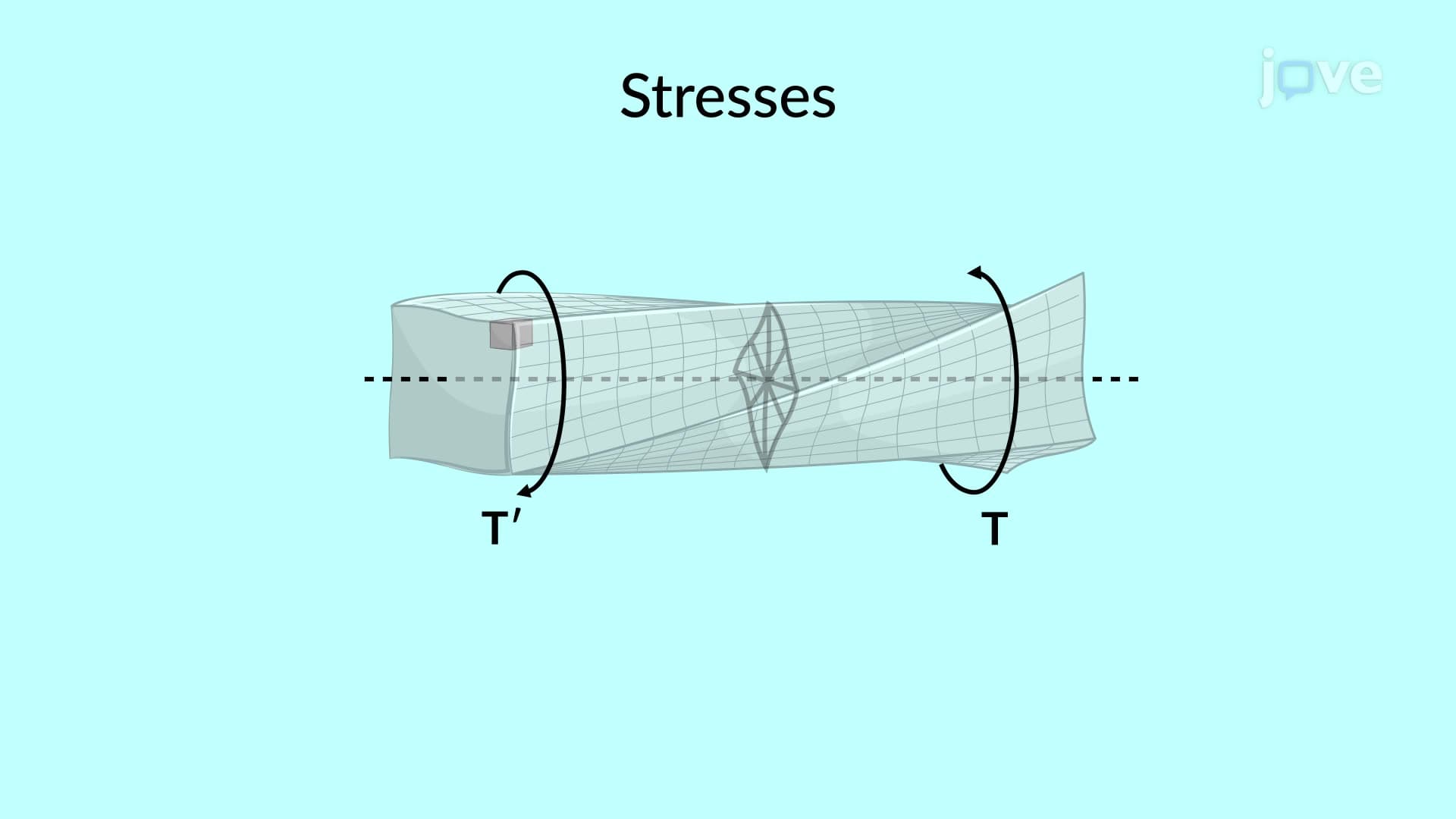
When engineering students first encounter the elastic torsion formula (τ = Tr/J), they learn to calculate shear stress in perfectly uniform circular shafts. However, real-world applications rarely involve such idealized conditions. Stress concentration effects in circular shafts occur when geometric discontinuities, loading methods, or material changes disrupt the smooth stress flow predicted by basic torsion theory.
Sources of Stress Concentration in Practical Applications
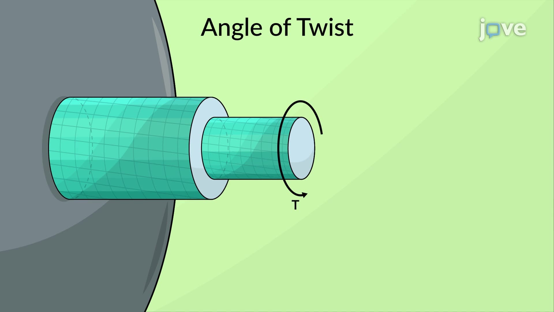
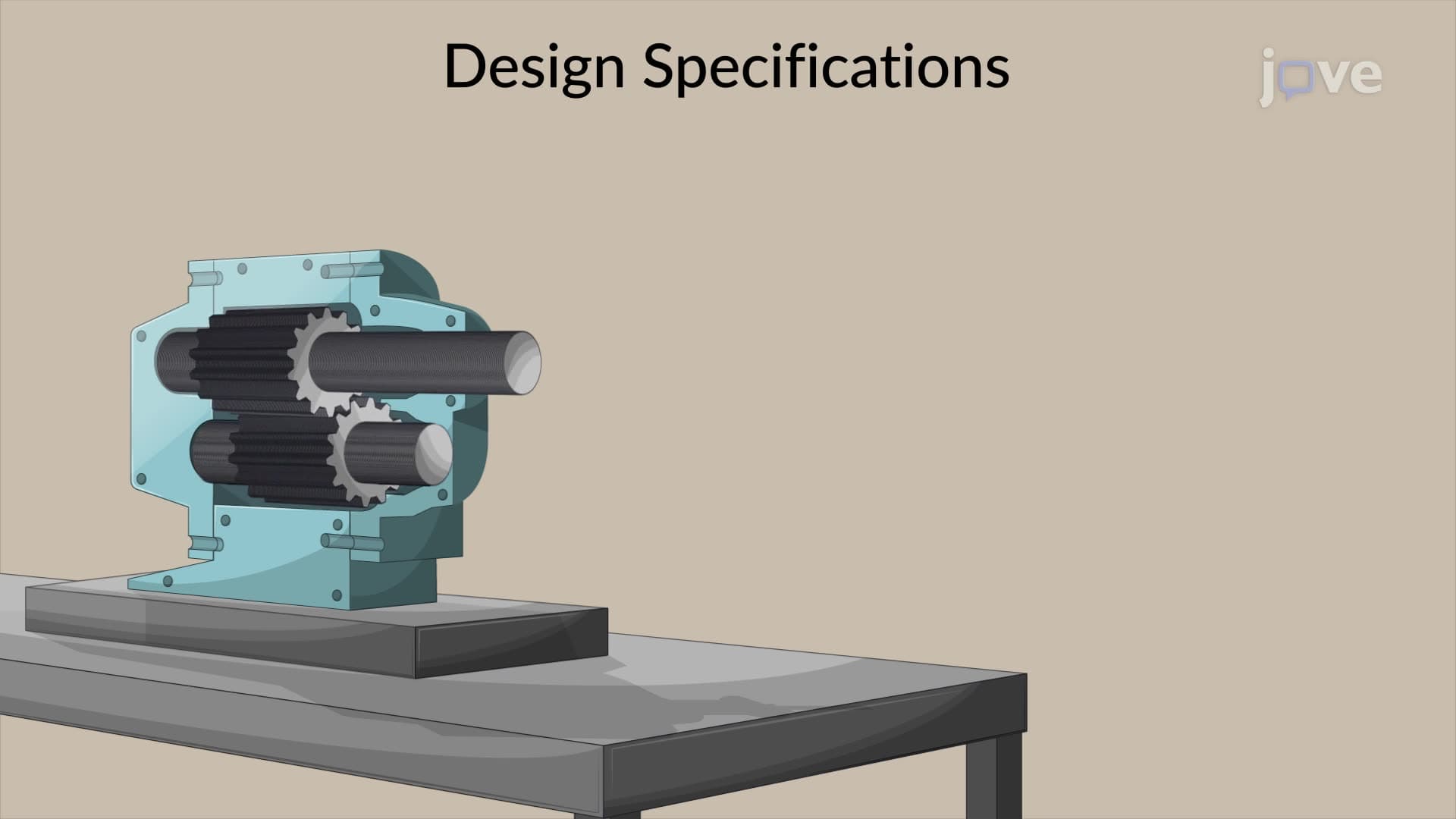
The most common culprits creating stress concentration include keyways cut into shafts for gear attachment, flange couplings that transfer torque through bolt patterns, and abrupt diameter changes at bearing locations. Consider a typical automotive driveshaft: where the universal joint connects, the shaft diameter must change to accommodate the joint hardware. This geometric transition creates a stress concentration zone where actual stresses can be 2-3 times higher than torsion formula predictions.
Quantifying Stress Concentration Through Design Factors
Engineers use stress concentration factors (Kt) to account for these effects mathematically. The relationship becomes: τ(max) = Kt × τ(nominal), where τ(nominal) comes from standard torsion calculations. These factors depend on geometric ratios like fillet radius to shaft diameter (r/d) and diameter ratios between adjacent shaft sections (D/d). For AP Physics C students, this represents a practical application of how mathematical models must be modified for real-world engineering problems.
Mitigation Strategies and Design Considerations
Fillets represent the primary tool for reducing stress concentrations. By creating smooth radius transitions instead of sharp corners, engineers can reduce stress concentration factors from potentially dangerous values (Kt = 3.0+) down to manageable levels (Kt = 1.5-2.0). The Boeing 737's engine mount shafts exemplify this principle, featuring carefully designed fillet radii at every diameter change to ensure safe stress levels throughout the aircraft's service life.
Understanding these concepts proves crucial for college-level mechanics of materials courses and professional engineering licensing exams, where students must demonstrate mastery of both theoretical foundations and practical design applications.
Frequently Asked Questions
Stress concentration effects occur when geometric features or loading methods cause localized stress values to exceed those predicted by standard torsion formulas. Common sources include keyways, diameter changes, and coupling attachments that disrupt uniform stress distribution. These effects can create dangerous failure points if not properly accounted for in design.
The AP Physics C mechanics exam typically tests this concept through problems involving torque applications and stress calculations in rotating systems. Students must recognize when basic torsion formulas apply versus when concentration factors become necessary. Free response questions often require explaining why real shafts behave differently than idealized uniform cylinders.
Absolutely - this concept forms a cornerstone of mechanics of materials and machine design courses at universities like MIT, Stanford, and Georgia Tech. Students learn to calculate stress concentration factors, design safe fillet radii, and analyze real engineering components. These skills directly transfer to professional engineering practice and FE exam preparation.
Automotive driveshafts, axles, and transmission components all require stress concentration analysis during design. Ford's engineers must ensure that keyway cuts for CV joints don't create failure points under maximum torque conditions. NASCAR teams particularly focus on these effects when designing high-performance drivetrain components that operate at extreme stress levels.
Not at all - the core concept builds naturally on basic torsion principles covered in AP Physics. Students who understand how force concentrates around holes in materials can easily grasp how geometric changes concentrate stress in rotating shafts. The mathematical complexity increases in college, but the fundamental physics remains accessible.
Focus on identifying sources of concentration first, then practice applying concentration factors to basic torsion calculations. Create a reference sheet of common Kt values for different geometric ratios. Work through problems involving both analysis (given geometry, find maximum stress) and design (specify fillet radius for safe operation).
Progress to fatigue analysis, where stress concentrations become critical for predicting component life under repeated loading. Combined loading scenarios (torsion plus bending) and three-dimensional stress concentration effects represent natural next steps. Finite element analysis methods for complex geometries offer cutting-edge applications of these principles.
Stress concentrations often initiate crack formation and propagation, making them critical for fracture mechanics analysis. Brittle materials like cast iron are particularly sensitive to these effects, while ductile materials can sometimes redistribute stress through localized yielding before catastrophic failure occurs.
Related Micro-courses

18 Concepts
4 Concepts
