Loading subject page…

- Mechanical Engineering
- Torsion
- Stresses in a Shaft
Micro-course: Torsion
5,181 views
Learn key concepts and earn your certificate.

Stresses in a Shaft

00:00
01:18
Video Summary: What Is Stresses in a Shaft
Ever wonder why the drive shaft in a Ford F-150 doesn't snap when hauling a heavy trailer up steep mountain roads? Stresses in a shaft occur when rotating mechanical components experience twisting forces called torques, creating internal shearing stresses that engineers must carefully calculate. These stresses determine whether critical components like automotive drive shafts, wind turbine rotors, or industrial machinery will safely handle their intended loads. Understanding what is stresses in a shaft helps predict failure points and design reliable mechanical systems. Watch the full video on JoVE Coach to master this concept with expert-led visuals and step-by-step explanations.
- Understand the fundamental mechanics of stresses in a shaft and how torques create internal shearing forces in rotating components
- Identify the relationship between applied torque, shaft geometry, and the resulting stress distribution across circular cross-sections
- Analyze free-body diagrams to determine equilibrium conditions and internal force relationships in twisted shafts
- Apply the basic torque-stress equation (T = τ × r × A) to calculate shearing stresses at different radial distances from the shaft axis
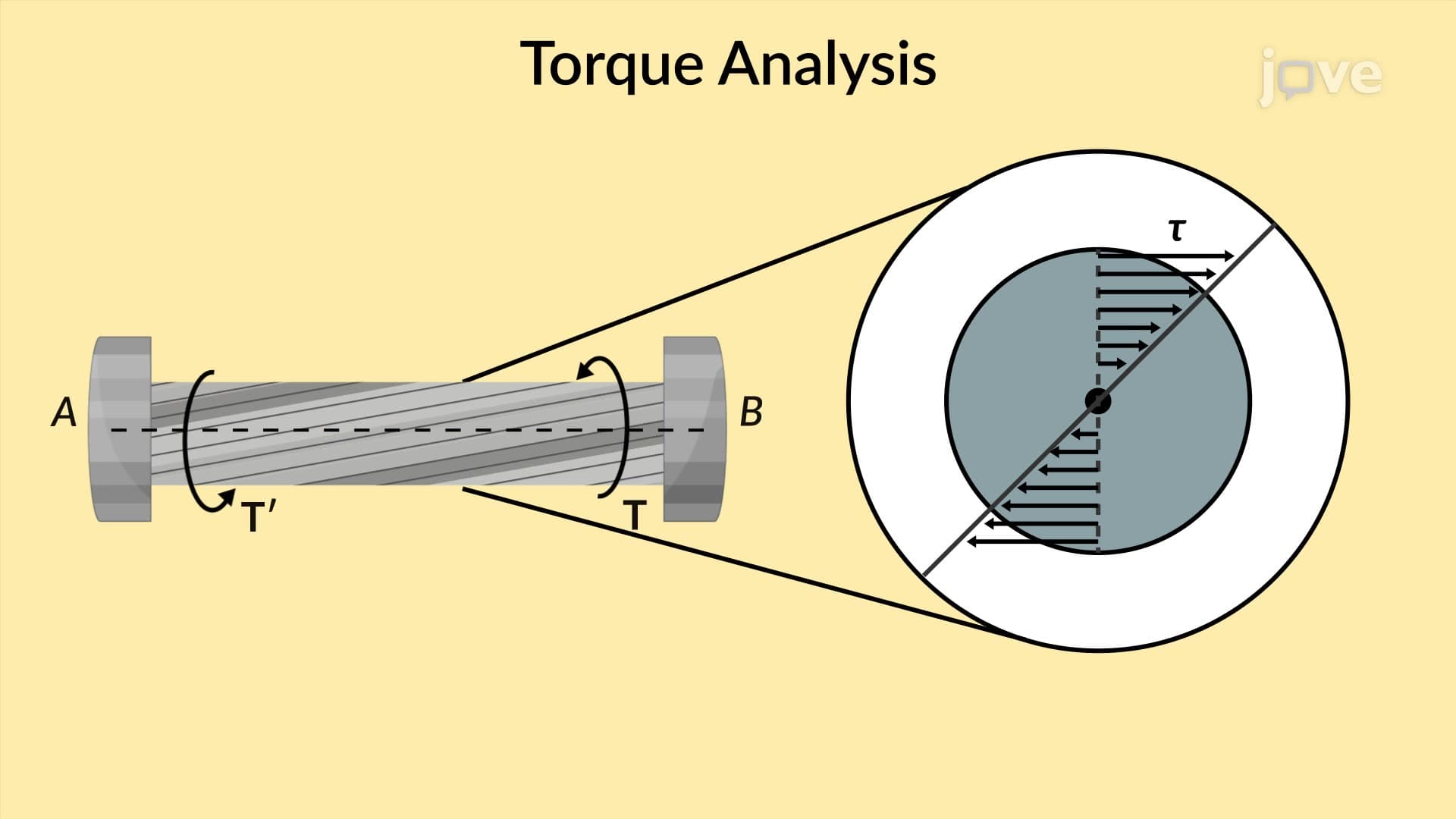
- Recognize that shearing stress varies linearly from zero at the center to maximum values at the outer surface of solid circular shafts
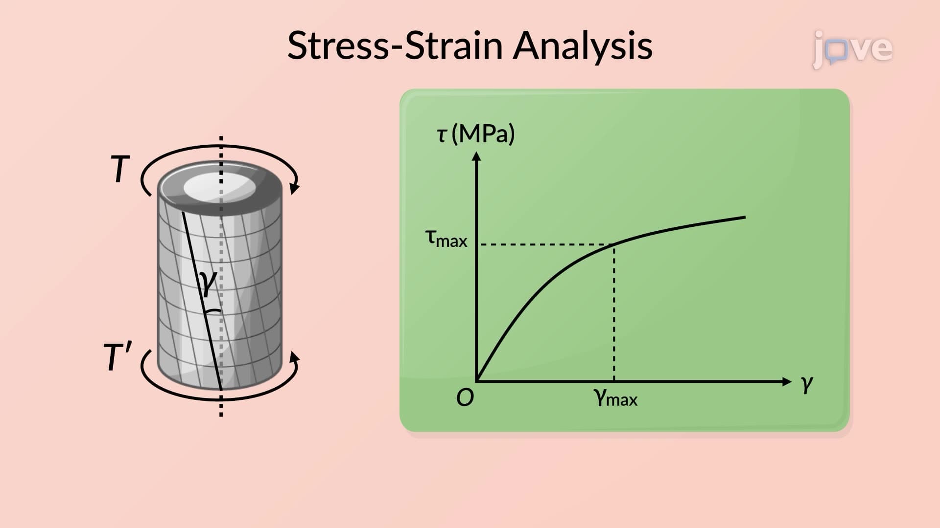
- Evaluate why static analysis alone cannot determine complete stress distribution patterns without considering material deformation
- Compare stress concentrations in different shaft geometries and cross-sectional shapes used in engineering applications
- Explore the connection between torsional shear stress theory and real-world mechanical design problems in automotive and aerospace industries
Understanding Stresses in A Shaft Fundamentals
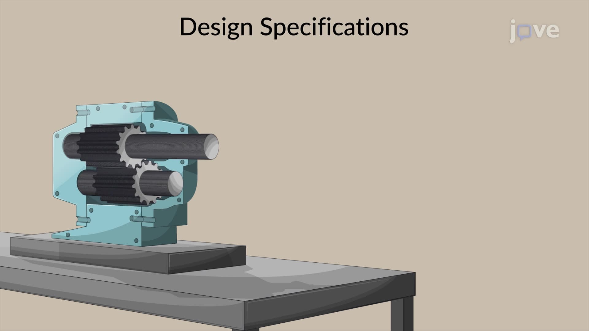
Stresses in a shaft represent one of the most critical concepts in mechanical engineering, describing how rotating components respond to twisting loads. When a shaft experiences torque-like the crankshaft in a Chevrolet Camaro's V8 engine-internal shearing stresses develop throughout the material. These stresses aren't uniformly distributed; they follow predictable patterns that engineers use to prevent catastrophic failures in everything from airplane propellers to oil drilling equipment.
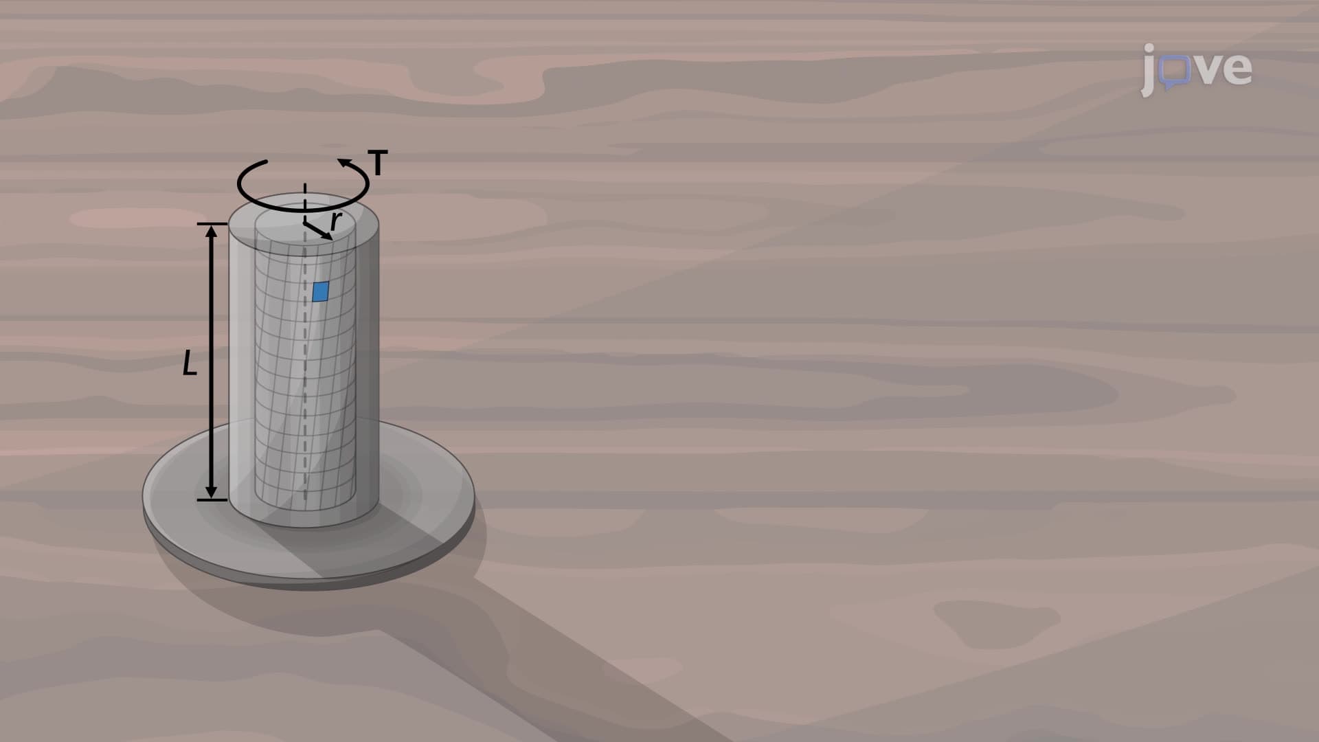
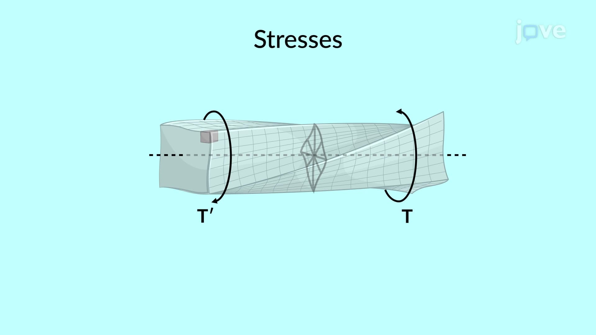
The physics begins with equilibrium analysis. Consider a steel shaft subjected to equal and opposite torques at its ends, similar to how a socket wrench applies rotational force to a bolt. By examining a cross-sectional "slice" through the shaft, we can analyze the internal forces required to maintain equilibrium. The shearing forces within any cross-section must balance the applied external torque, creating the fundamental relationship: T = ∫(τ × r × dA), where τ represents shearing stress, r is the radial distance from the center, and dA represents a small area element.
Stress Distribution and Mathematical Relationships
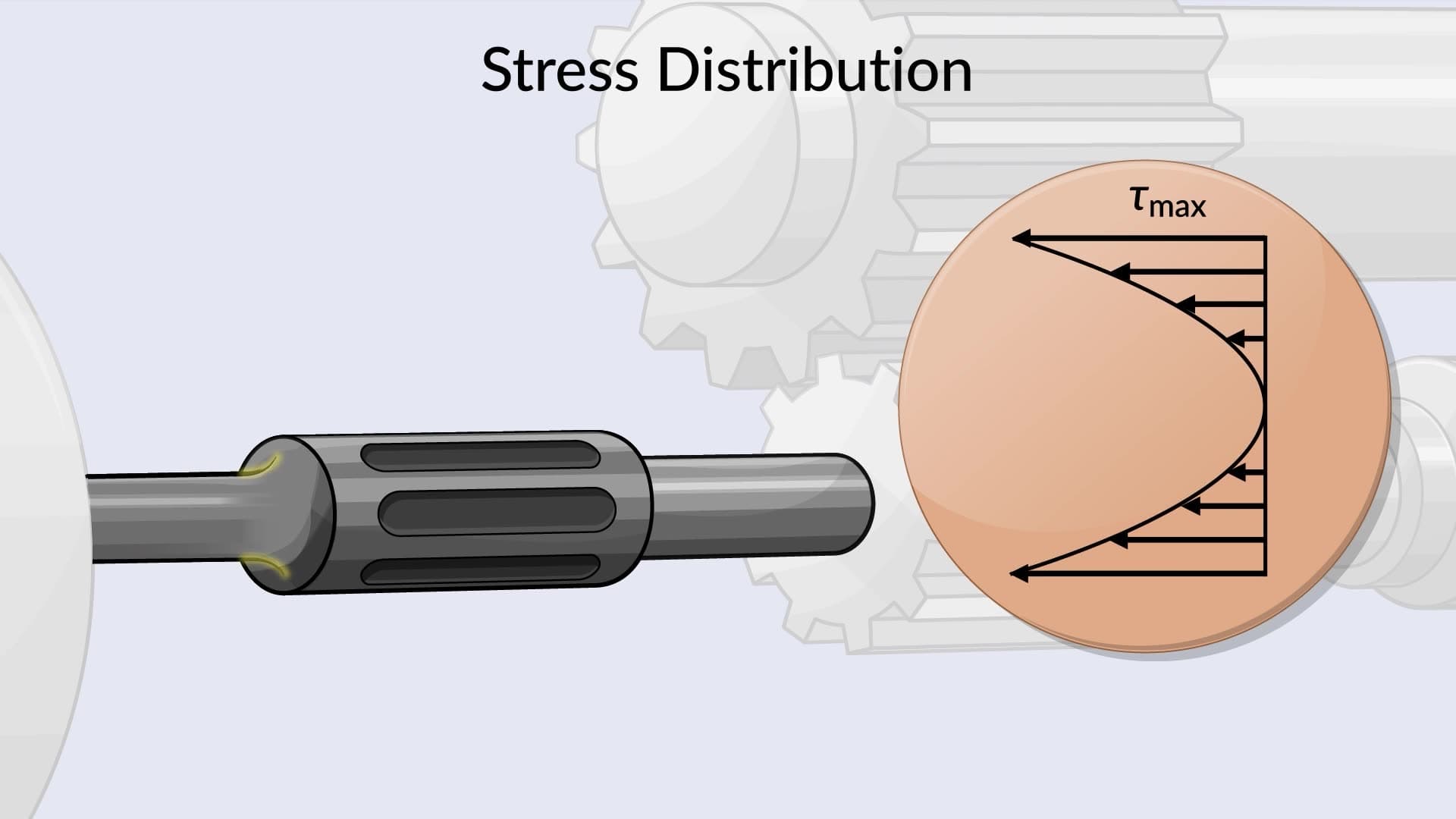
The stresses in a shaft overview reveals that shearing stress varies linearly with radial position. At the shaft's centerline, shearing stress equals zero because r = 0. Maximum stress occurs at the outer surface where r reaches its maximum value. This linear distribution means that hollow shafts can be highly efficient-removing material from the low-stress center reduces weight while maintaining strength, which is why bicycle frames and aircraft components often use tubular designs.
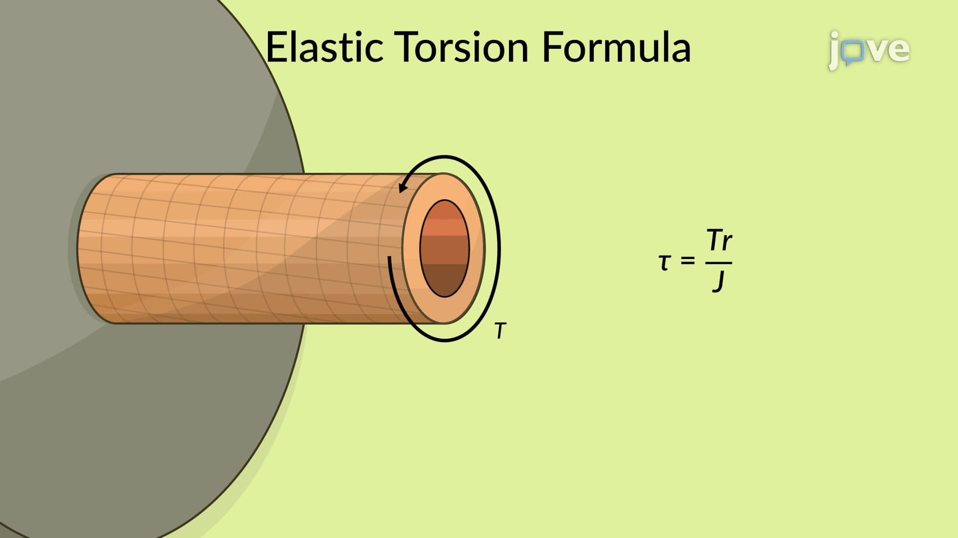
For solid circular shafts with radius R, the maximum shearing stress becomes τ(max) = TR/J, where J represents the polar moment of inertia (J = πR⁴/2 for solid circles). This equation appears frequently on AP Physics exams and college-level Statics courses, making it essential for students pursuing engineering degrees at institutions like MIT, Stanford, or Georgia Tech.
Real-World Applications and Engineering Significance
Understanding what is stresses in a shaft in detail proves crucial for numerous American industries. Boeing engineers use these principles when designing aircraft engine shafts that must withstand extreme rotational speeds. Ford's transmission engineers apply torsional stress calculations to ensure drive shafts can handle maximum engine torque without failure. Wind energy companies like GE Renewable Energy rely on these concepts to design turbine shafts capable of converting wind power into electricity for decades.
The stresses in a shaft concept also explains why failures often occur at stress concentration points-locations where geometry changes create local stress amplifications. Keyways, shoulders, and other discontinuities can increase local stresses by factors of 2-3 times the nominal calculated values, requiring careful attention in design phases.
Frequently Asked Questions
Stresses in a shaft are internal shearing forces that develop when rotating components experience twisting loads called torques. These stresses determine whether mechanical components will safely handle their intended loads or fail catastrophically. Understanding these stresses is essential for designing everything from car transmissions to wind turbine generators, making this concept fundamental to mechanical engineering education and professional practice.
AP Physics C and college Statics courses frequently test torsional stress calculations using the equation τ(max) = TR/J for circular shafts. Exam problems typically provide torque values and shaft dimensions, requiring students to calculate maximum shearing stress and compare it to material strength limits. Many problems also involve determining required shaft diameters for given safety factors.
While the MCAT focuses more on biological applications, physics sections may include rotational mechanics problems where understanding torque and stress relationships helps solve questions about bone mechanics or medical device functionality. The underlying physics principles remain consistent across applications, making this knowledge valuable for pre-med students.
Automotive engineers at companies like General Motors and Tesla apply torsional stress analysis when designing drive shafts, axles, and transmission components. For example, calculating whether a truck's drive shaft can handle maximum engine torque when towing heavy trailers requires understanding how shearing stresses distribute across the shaft's cross-section and comparing these to material failure limits.
The basic concepts are accessible to high school physics students using algebra and trigonometry. While complete derivations involve calculus, the fundamental relationships like τ = TR/J can be understood and applied using arithmetic calculations. Starting with conceptual understanding of how twisting creates internal forces makes the mathematical relationships more intuitive.
Focus on drawing clear free-body diagrams and understanding the physical meaning behind each equation variable. Practice problems involving different shaft geometries and loading conditions, always checking that your calculated stresses have reasonable magnitudes. Create a formula sheet connecting torque, geometry, and material properties, and work through examples from different engineering applications.
Natural progressions include combined loading scenarios where shafts experience both torsion and bending, fatigue analysis for components under cyclic loading, and advanced topics like stress concentrations around geometric discontinuities. Students interested in design applications should explore shaft coupling methods and power transmission calculations used in mechanical systems.
Related Micro-courses

18 Concepts
4 Concepts
