Loading subject page…


18,675 views

Video Summary: What are First Order Circuits
Ever wondered why your smartphone's flash charges so quickly between photos? The answer lies in rc circuit without source behavior within first-order circuits. These electrical networks contain resistors paired with a single energy storage element-either a capacitor or inductor-creating predictable charging and discharging patterns. From camera flash units in iPhones to fluorescent lighting systems across American schools and offices, first order circuits govern countless everyday technologies through their characteristic exponential responses. Watch the full video on JoVE Coach to master this concept with expert-led visuals and step-by-step explanations.
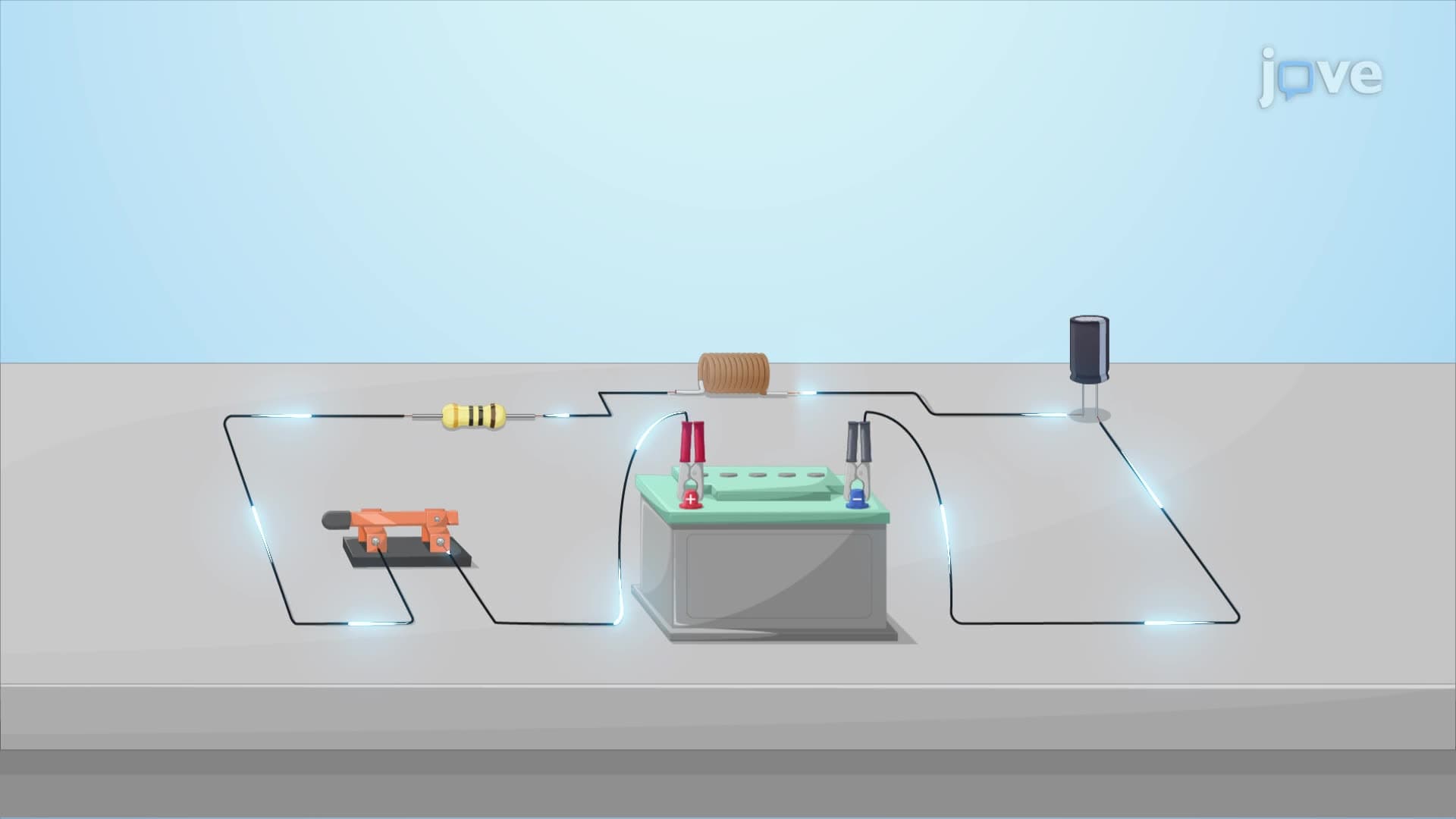
First order circuits represent one of the most fundamental concepts in electrical engineering, characterized by containing exactly one energy storage element (capacitor or inductor) combined with resistive elements. The term "first-order" derives from the mathematical reality that these circuits are governed by first-order differential equations, making them relatively straightforward to analyze compared to more complex multi-element systems.
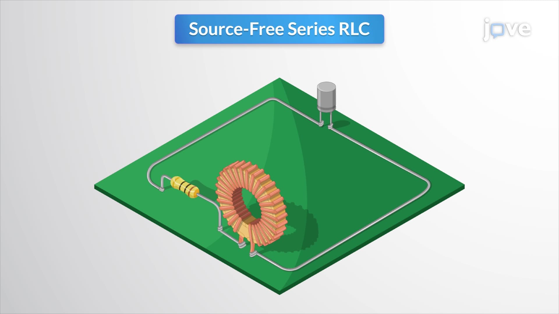
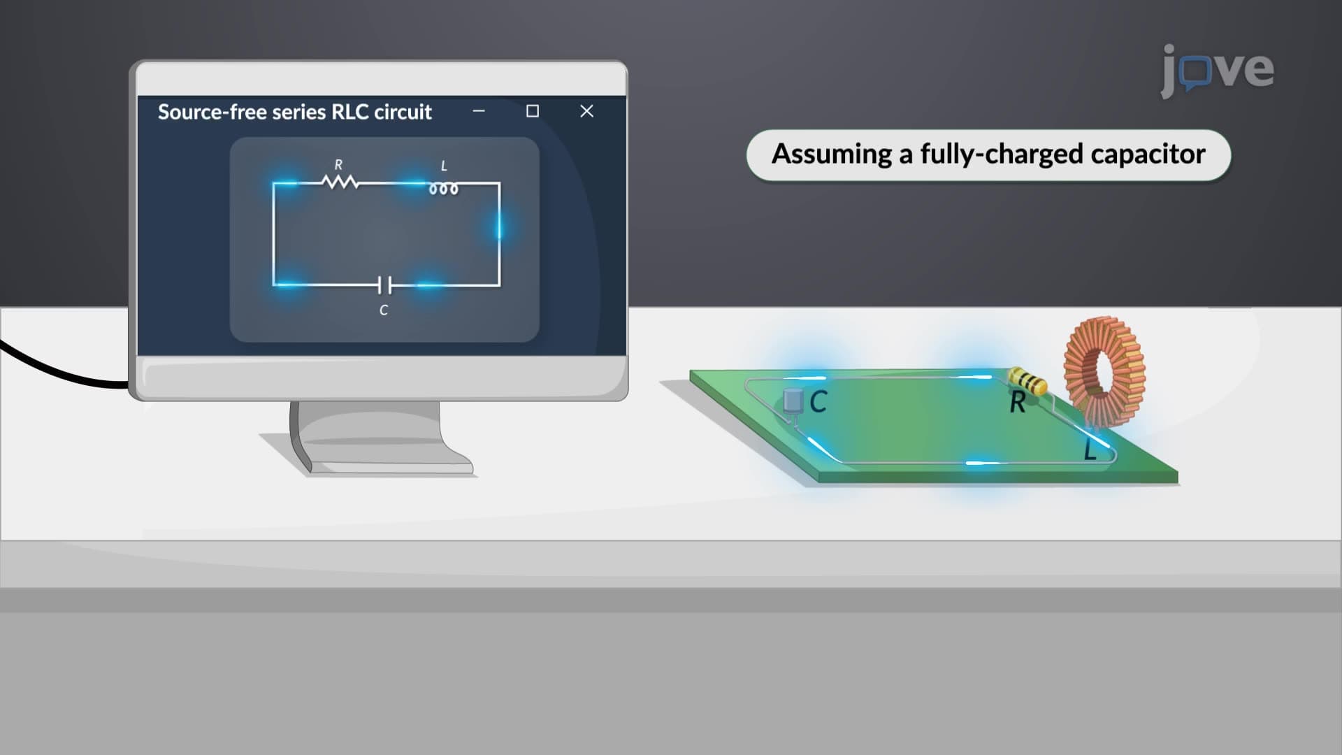
The rc circuit without source scenario specifically refers to analyzing these circuits during their natural response-examining how stored energy dissipates when no external voltage or current sources are present. This analysis proves crucial for understanding everything from camera flash recycling times to the decay characteristics of electronic filters used in audio equipment throughout American recording studios.
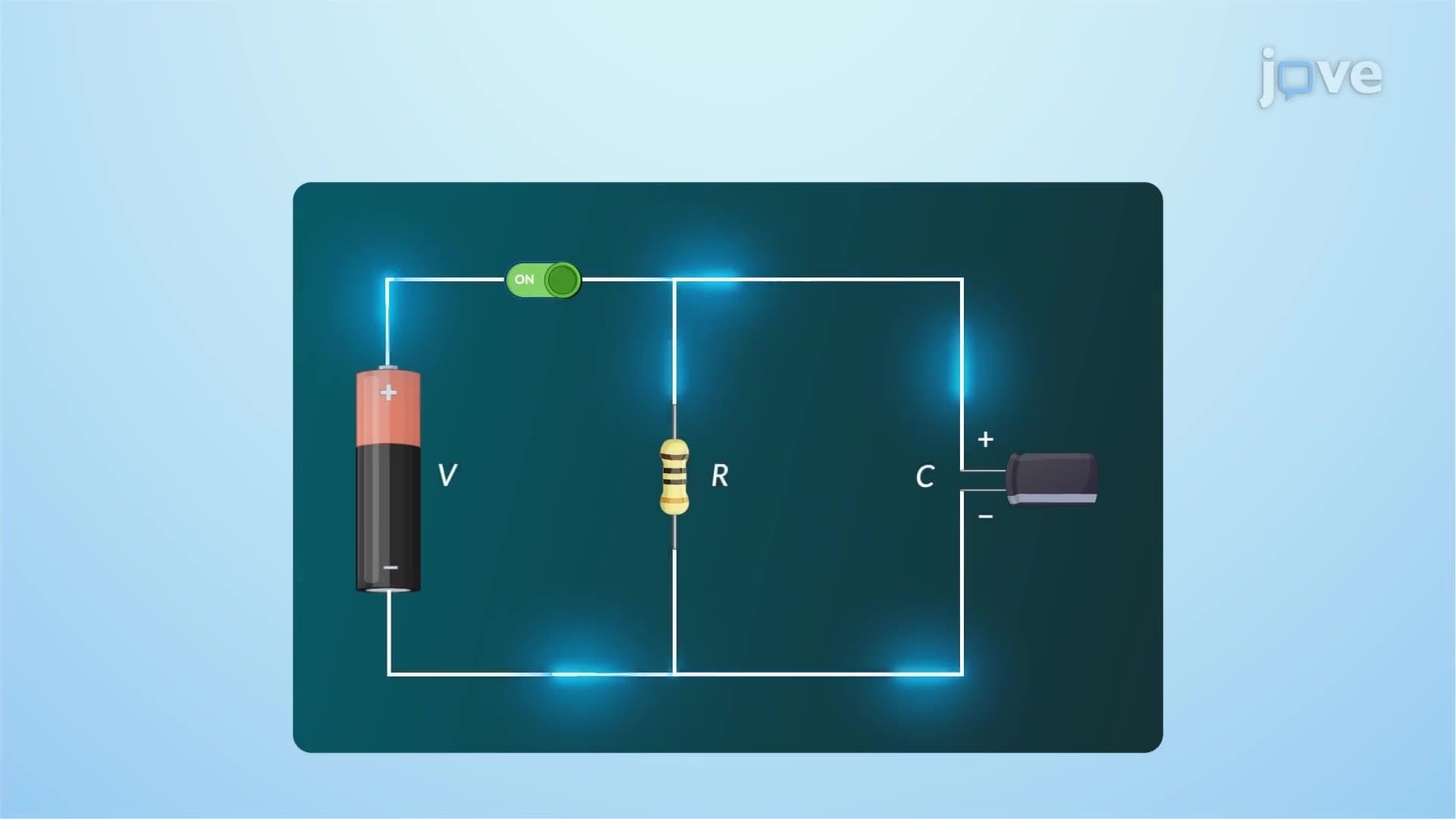
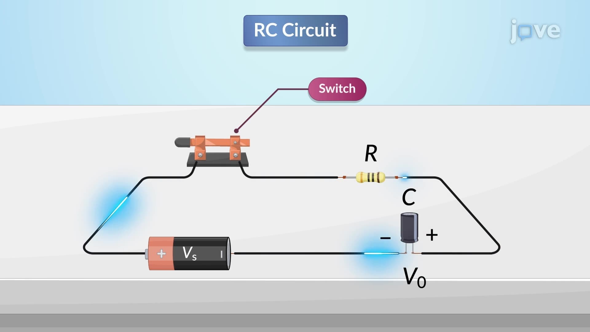
RC circuits combine resistors with capacitors, creating systems where electrical energy stores in the capacitor's electric field. When examining an rc circuit without source definition, we focus on the exponential decay process as the capacitor discharges through the resistor. The time constant τ = RC determines how quickly this discharge occurs, with the capacitor losing approximately 63% of its initial voltage after one time constant period.
Students preparing for AP Physics or college-level circuit analysis courses frequently encounter problems involving RC circuits in timing applications. Consider the ubiquitous 555 timer IC found in countless American-made electronic devices-its operation fundamentally depends on RC time constant principles. The rc circuit without source concept becomes particularly relevant when analyzing how these circuits behave between active input pulses.
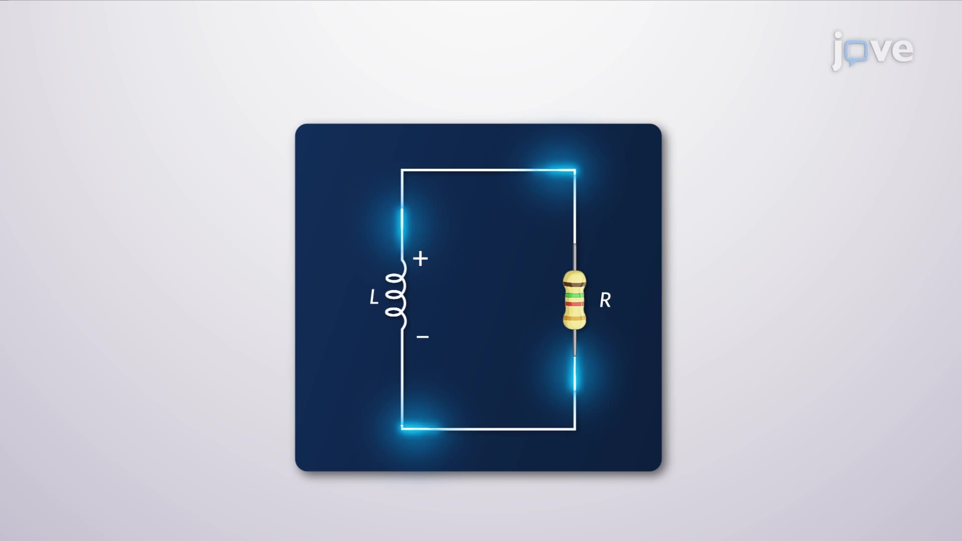
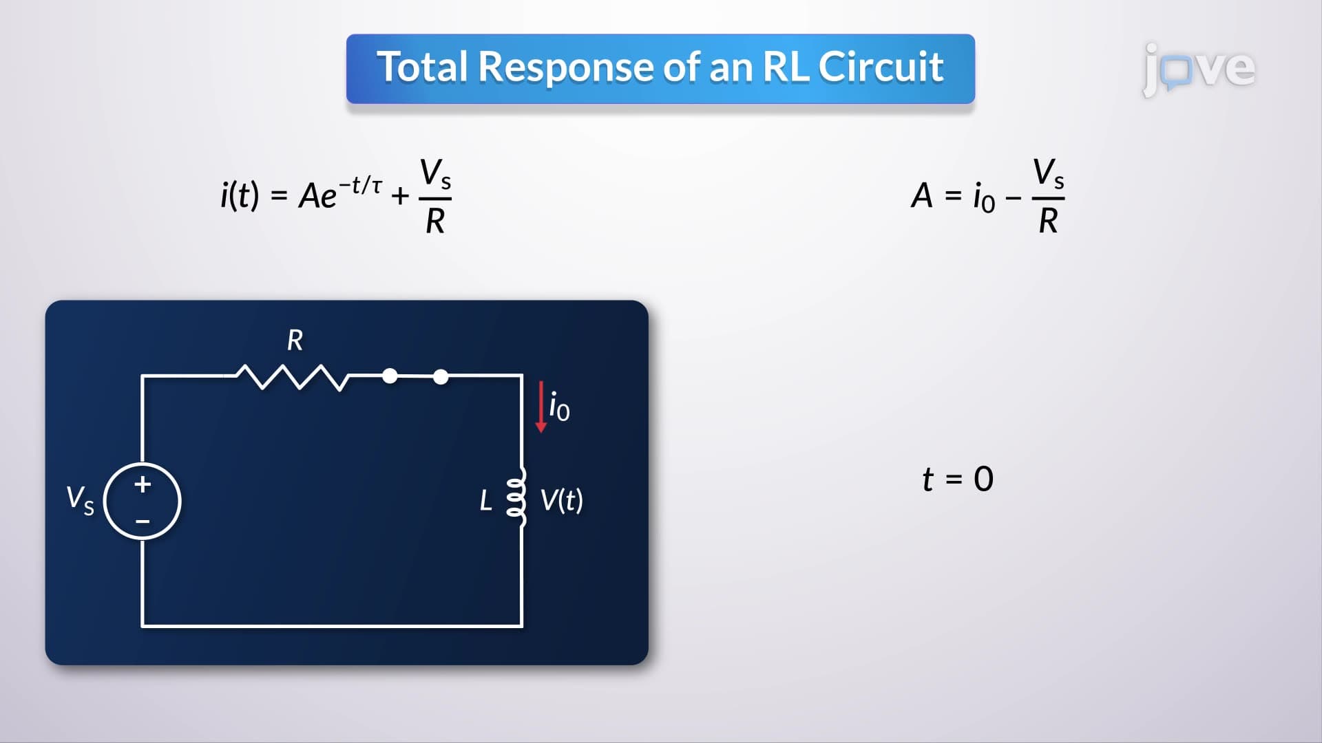
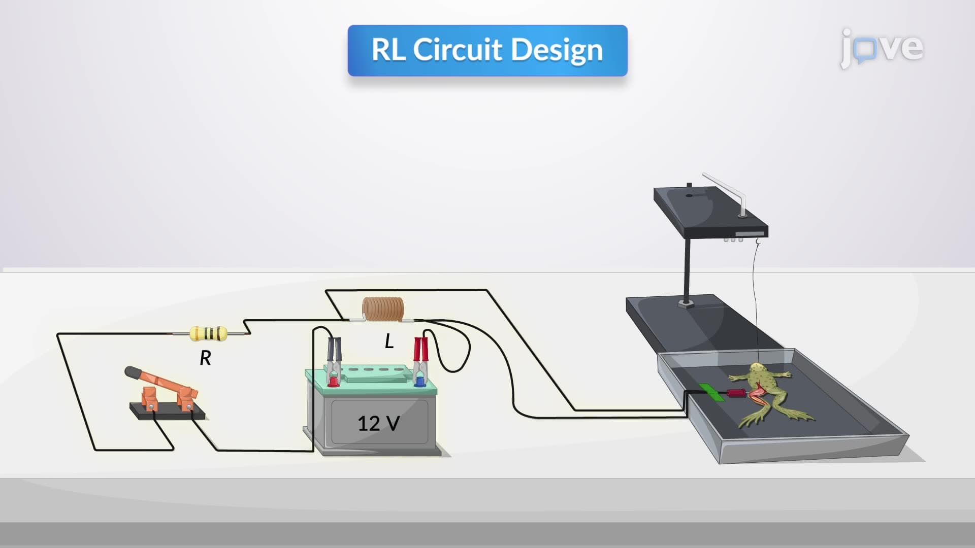
RL circuits pair resistors with inductors, where energy storage occurs in the inductor's magnetic field. Unlike capacitors that oppose voltage changes, inductors resist current changes, creating different mathematical relationships. The time constant for RL circuits equals L/R, where L represents inductance and R represents resistance.
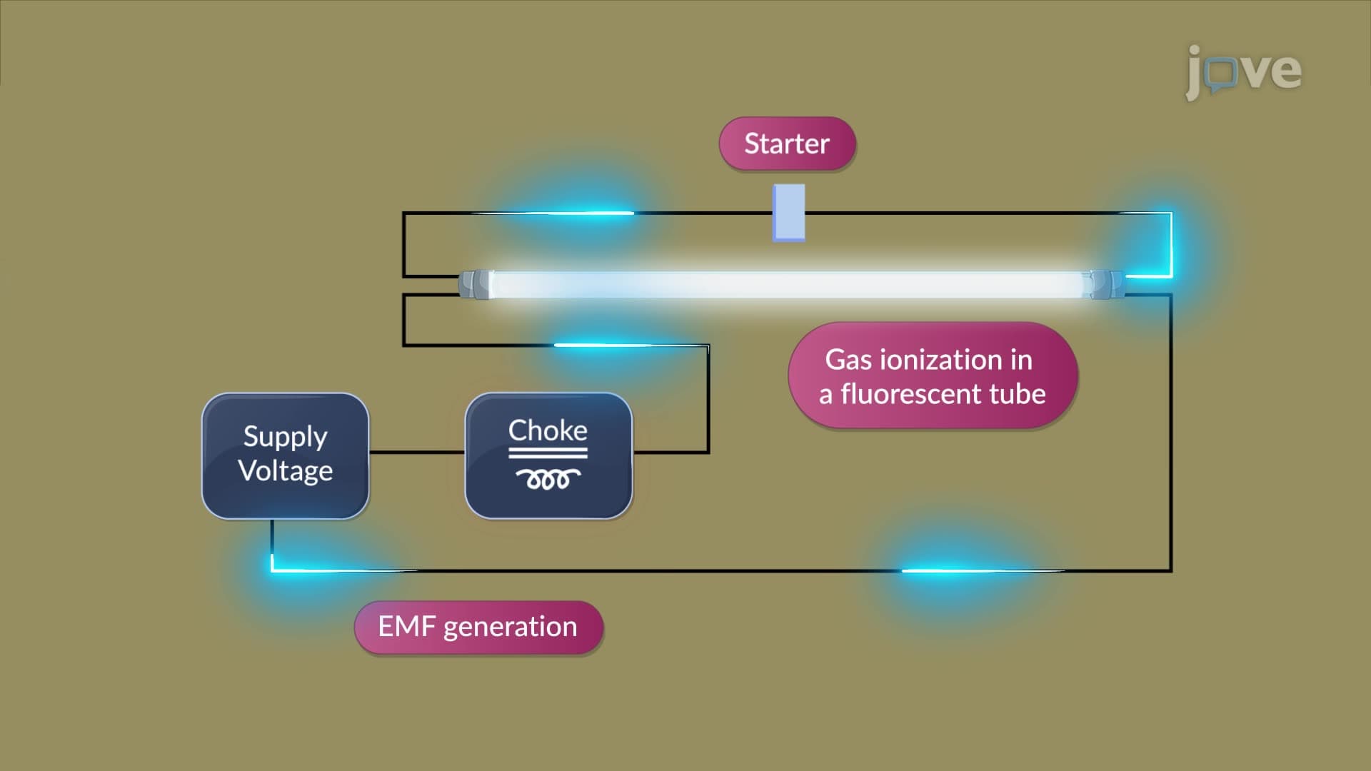
American fluorescent lighting systems, commonly found in schools and offices, exemplify practical RL circuit applications. The ballast (choke) functions as the inductor, working with the circuit's inherent resistance to control current flow during tube ignition. Understanding rc circuit without source overview principles helps students grasp why these systems require brief startup delays-the inductive elements need time to establish proper magnetic fields.
Both RC and RL first-order circuits follow exponential mathematical relationships, but with inverse behaviors. RC circuits exhibit exponential voltage decay and current decay, while RL circuits show exponential current rise and voltage changes. These mathematical patterns appear frequently in standardized tests like the MCAT physics section, where students must quickly identify circuit types and predict their temporal responses.
The rc circuit without source study guide approach emphasizes recognizing these exponential patterns in various contexts, from cardiac pacemaker circuits in medical devices approved by the FDA to automotive electronic control units manufactured in American facilities.
Related Micro-courses