Loading subject page…

- Electrical Engineering
- First and Second Order Circuits
- Parallel RLC Circuits
Micro-course: First and Second-Order Circuits
18,675 views
Learn key concepts and earn your certificate.


Parallel RLC Circuits


00:00
01:14
Video Summary: What are Parallel Rlc Circuits
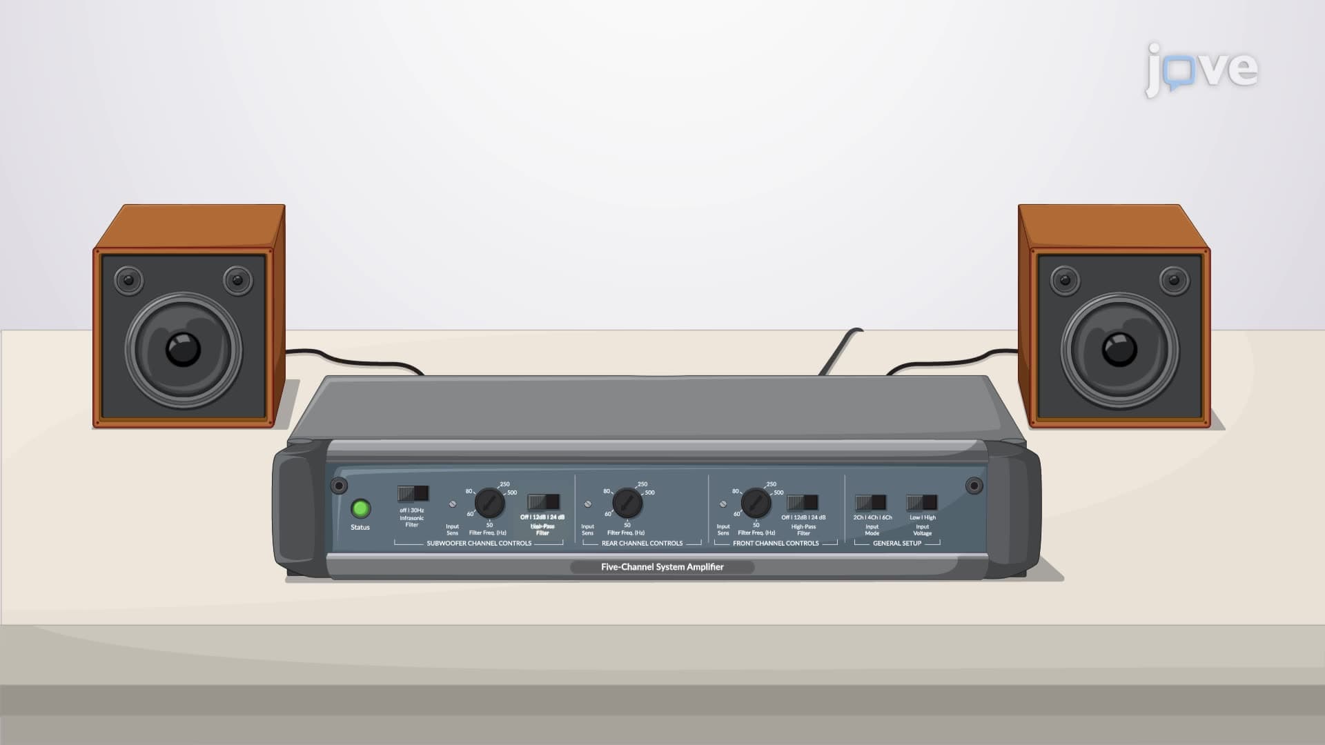
Ever wondered how street lamps survive lightning strikes without burning out? Second order op amp circuits and parallel RLC configurations provide the answer through sophisticated surge protection systems. In major US cities like New York, these parallel RLC circuits protect millions of electrical devices daily from voltage spikes that could otherwise cause catastrophic failures. These circuits combine resistors, inductors, and capacitors in parallel arrangements to create predictable responses to electrical disturbances. Watch the full video on JoVE Coach to master this concept with expert-led visuals and step-by-step explanations.
- Understand how parallel RLC circuits function as fundamental building blocks in electrical engineering and their role in surge protection systems
- Identify the three distinct damping responses (overdamped, critically damped, and underdamped) that characterize second-order circuit behavior
- Analyze transient and steady-state responses using Kirchhoff's current law and second-order differential equations
- Compare how damping factors relative to resonant frequency determine circuit response characteristics
- Apply initial condition analysis to determine unknown constants in complete circuit solutions
- Evaluate real-world applications of parallel RLC circuits in power grid protection and electronic device safety
- Recognize the mathematical relationship between circuit parameters and response behavior
- Explore the connection between source-free and driven circuit responses in practical engineering scenarios
Understanding Parallel RLC Circuits Fundamentals
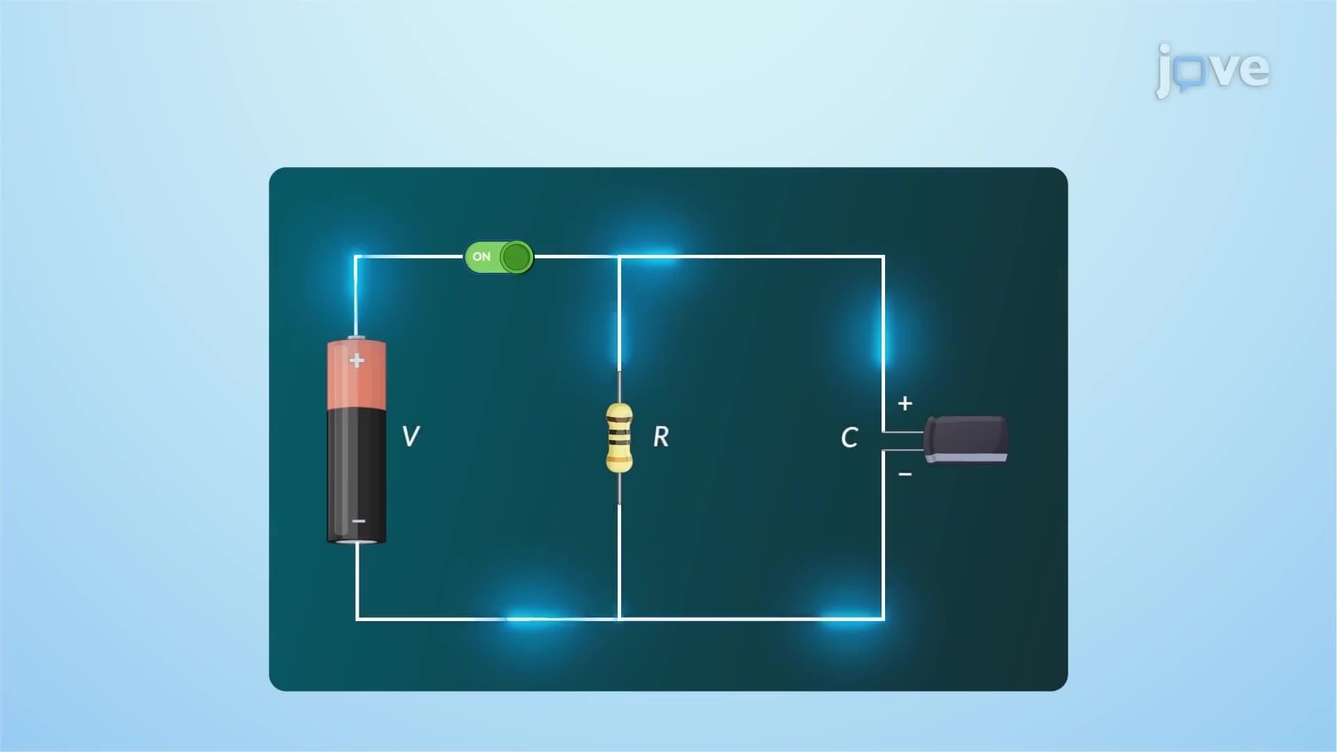
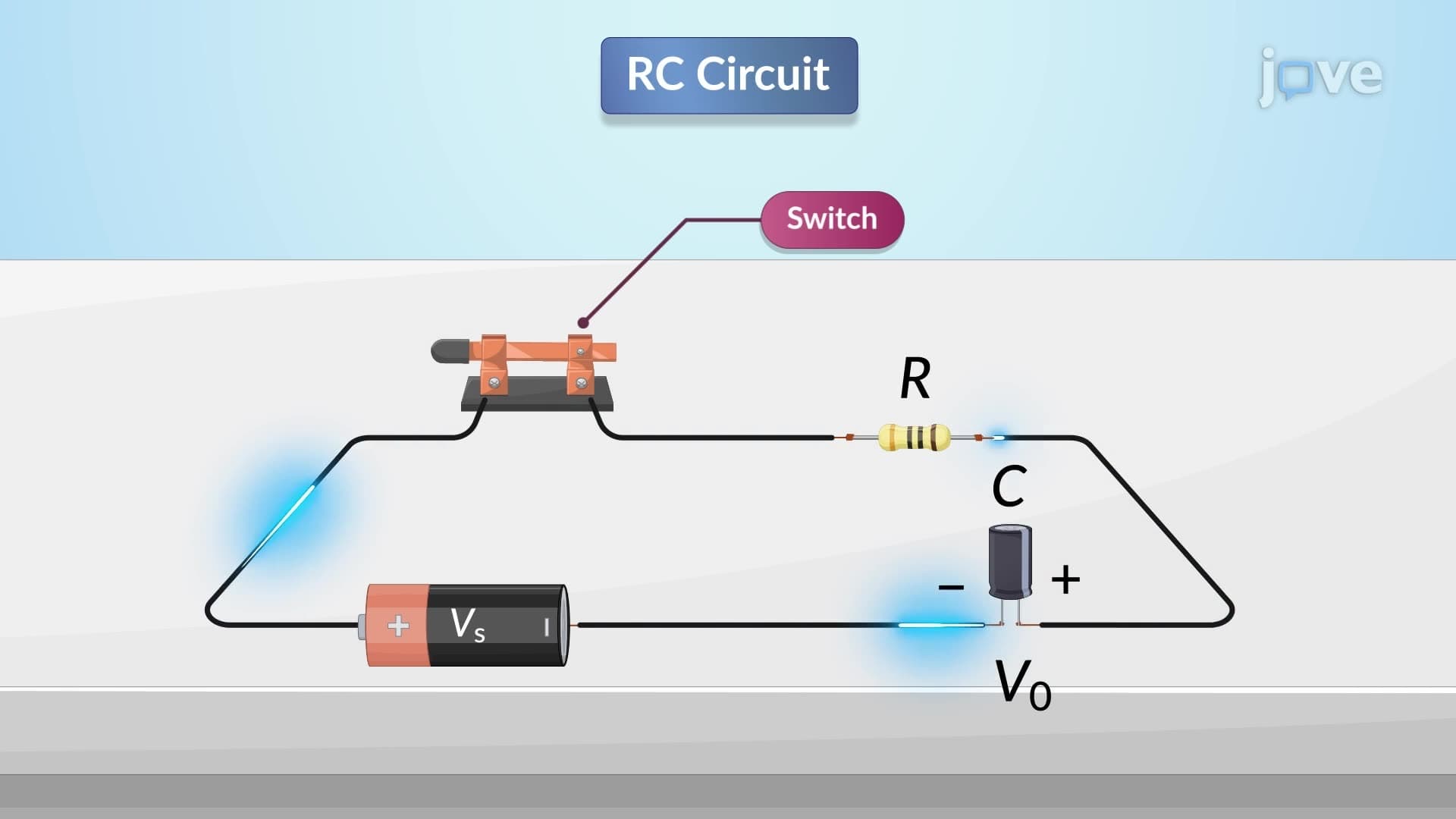
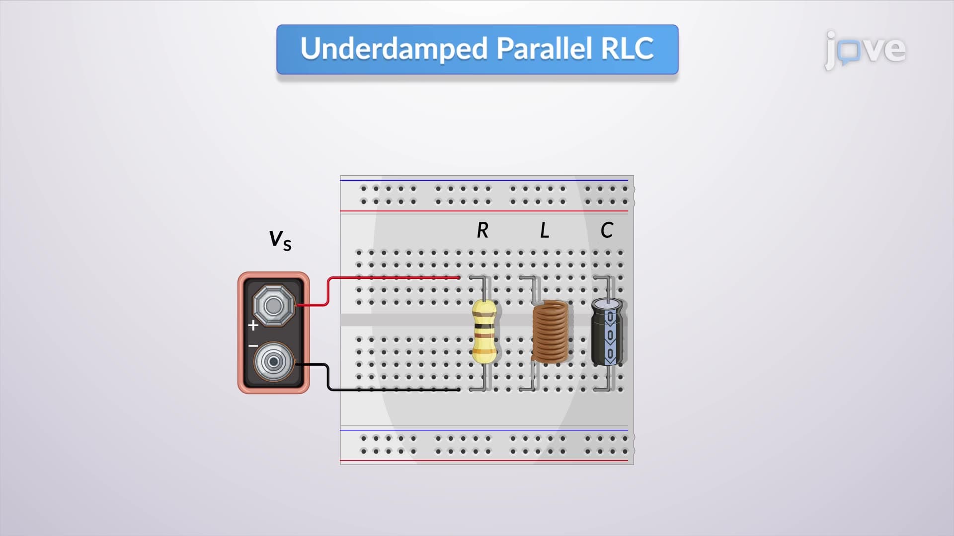
Parallel RLC circuits represent one of the most important configurations in electrical engineering, where resistors (R), inductors (L), and capacitors (C) are connected in parallel across a common voltage source. Unlike their series counterparts, parallel arrangements allow each component to experience the same voltage while carrying different currents. This configuration is particularly valuable in second order op amp circuits where precise control of frequency response and stability is essential.
The mathematical foundation of these circuits rests on Kirchhoff's current law, which states that the sum of currents entering a node equals the sum of currents leaving. When applied to the top node of a parallel RLC circuit, this principle yields a second-order differential equation that governs the circuit's behavior. Students preparing for the AP Physics C exam or college-level circuits courses will encounter this as a cornerstone concept that bridges theoretical mathematics with practical engineering applications.
Damping Response Characteristics in Second Order Systems
The behavior of second order op amp circuits is fundamentally determined by the relationship between the damping factor and the natural resonant frequency. This relationship creates three distinct response types that engineers must understand for effective circuit design. In overdamped responses, where the damping factor exceeds the resonant frequency, the circuit returns to steady state gradually without oscillation-imagine a heavy door with a strong spring closing slowly without bouncing.
Critically damped responses occur when the damping factor exactly equals the resonant frequency, producing the fastest return to steady state without overshoot. This condition is highly sought after in control systems and appears frequently on MCAT physics sections. Underdamped responses, where damping is less than the resonant frequency, create oscillatory behavior that gradually decreases in amplitude. Major US power companies like ConEd in New York specifically engineer their surge protection systems to avoid underdamped responses that could damage sensitive equipment.
Transient and Steady-State Analysis Applications
Understanding how second order op amp circuits works requires mastering both transient and steady-state analysis. The transient response represents the circuit's temporary behavior immediately after a disturbance, while the steady-state response describes the final, stable condition. In practical applications like the surge protectors used by Tesla's Supercharger network across the United States, engineers must carefully design these responses to protect expensive charging equipment from voltage spikes while maintaining efficient power delivery.
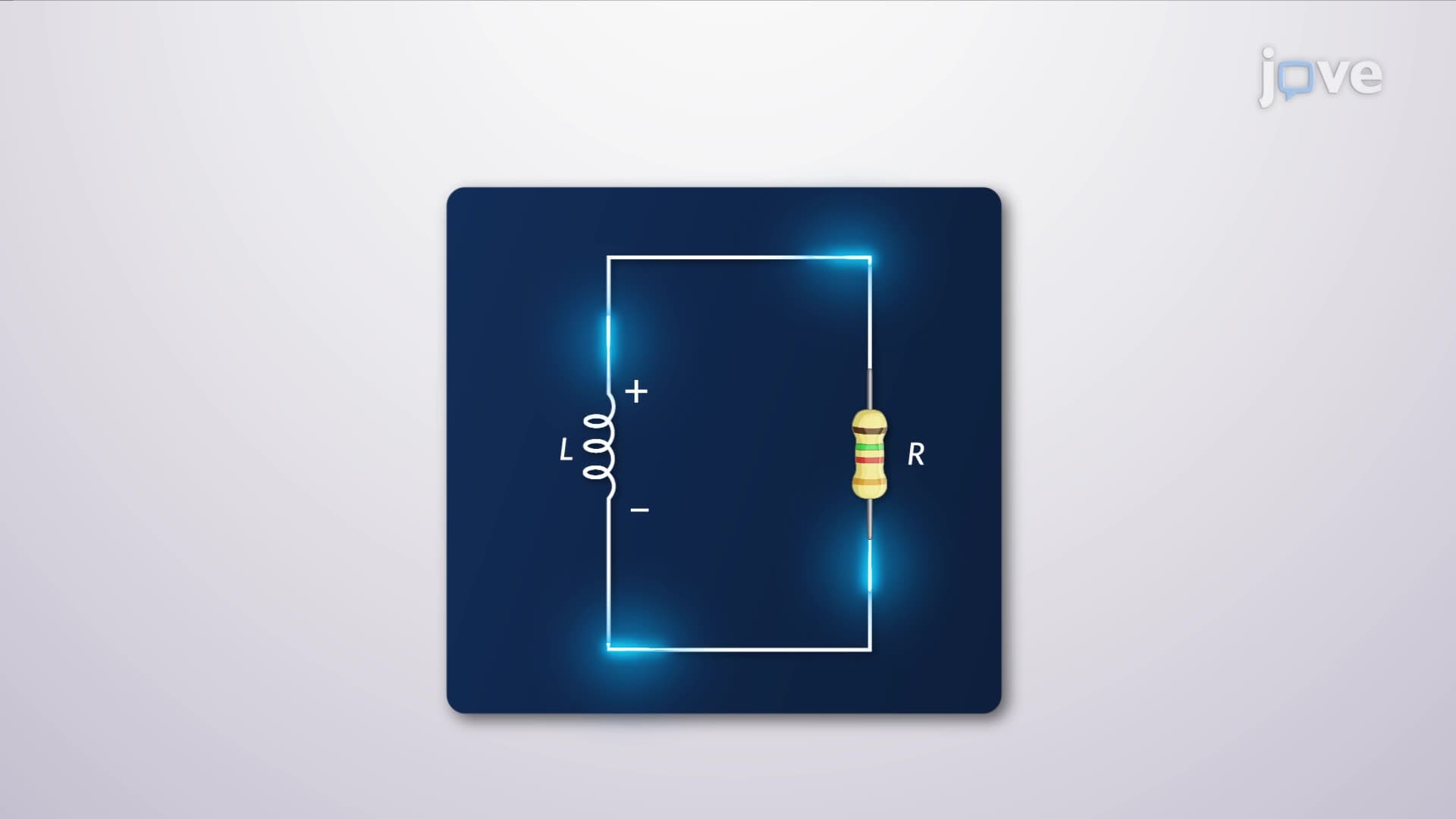
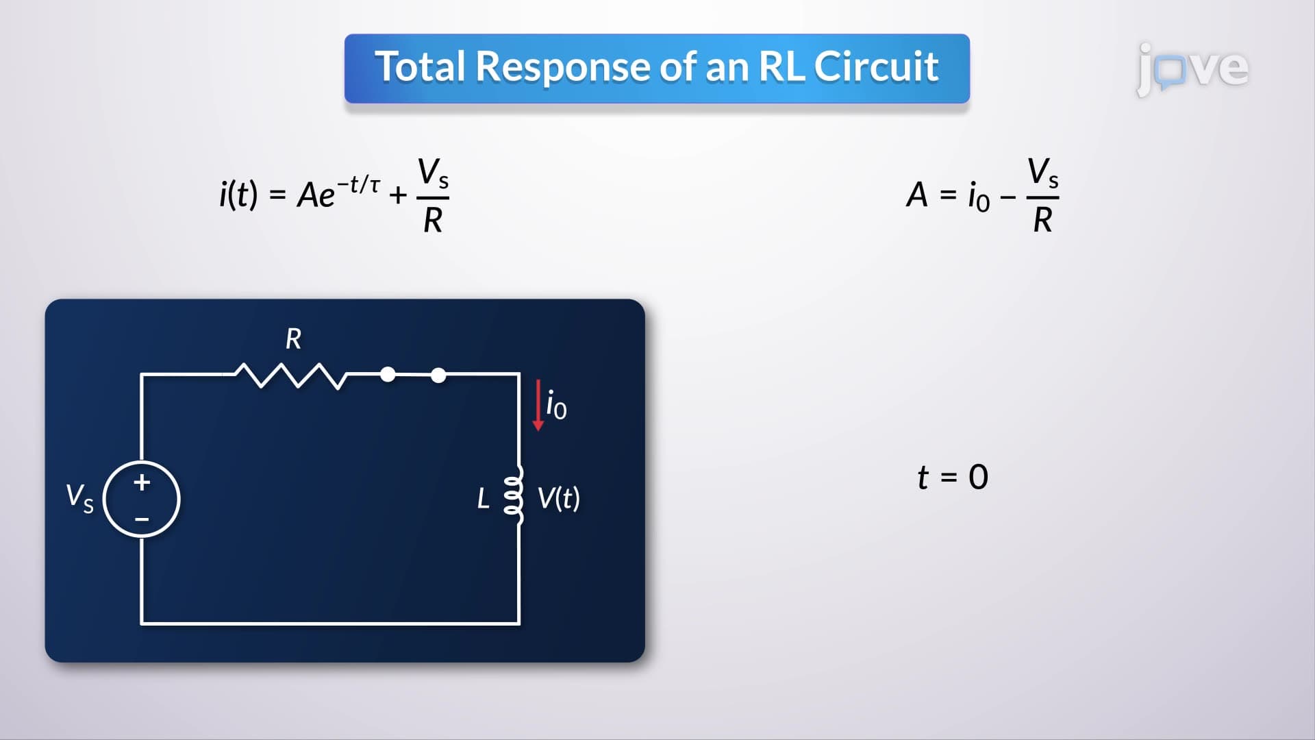
The complete solution combines both responses, with unknown constants determined by initial circuit conditions. Students studying for college midterms in electrical engineering programs at institutions like MIT or Stanford will frequently encounter problems requiring this type of analysis. The key insight is that eliminating the input source reveals purely transient behavior, demonstrating how external influences shape circuit response characteristics in real-world applications.
Frequently Asked Questions
Parallel RLC circuits connect resistors, inductors, and capacitors across the same voltage source, allowing each component to experience identical voltage while carrying different currents. Unlike series circuits where current remains constant and voltage divides, parallel configurations provide multiple current paths. This arrangement is essential in surge protection systems and power supply filtering applications throughout US infrastructure.
The AP Physics C exam typically includes parallel RLC circuit problems in the electricity and magnetism section, focusing on differential equation analysis and damping response identification. Students must demonstrate understanding of Kirchhoff's current law applications and transient response calculations. Practice with College Board released exams shows these concepts appear in both multiple-choice and free-response questions worth 10-15% of the total exam score.
Success requires solid foundations in calculus-based physics, differential equations, and complex number algebra typically covered in AP Calculus BC or college Calculus II. Most engineering programs at universities like UC Berkeley or Georgia Tech introduce these concepts in sophomore-level circuits courses. Students benefit from strong algebraic manipulation skills and comfort with exponential and sinusoidal functions.
Major applications include surge protectors in every American home, power grid stabilization systems managed by companies like Duke Energy, and noise filtering in smartphones manufactured by Apple and Google. Tesla's electric vehicle charging infrastructure relies heavily on parallel RLC configurations to protect against power quality issues. These circuits also appear in medical equipment used in US hospitals for patient monitoring and diagnostic imaging.
Compare the damping coefficient to the natural frequency: overdamped when damping exceeds natural frequency, critically damped when they're equal, and underdamped when damping is smaller. Visual inspection of response curves on exams reveals exponential decay for overdamped, fastest settling without overshoot for critical damping, and oscillatory decay for underdamped conditions. Practice problems from textbooks like Nilsson and Riedel help develop pattern recognition skills.
Focus on systematic problem-solving approaches starting with Kirchhoff's current law application, then differential equation formulation and solution. Create summary sheets linking mathematical expressions to physical behaviors observed in lab experiments. Form study groups to practice explaining damping concepts aloud, as teaching others reinforces understanding needed for both homework success and exam performance.
These circuits provide foundational understanding for control systems theory, signal processing, and power electronics studied in junior and senior engineering courses. Frequency domain analysis using Laplace transforms builds directly on parallel RLC concepts. Graduate programs and industry positions at companies like Intel or Qualcomm require deep familiarity with these second-order system behaviors for analog circuit design and electromagnetic compatibility testing.
The mathematical complexity of second-order differential equations combined with multiple response types creates conceptual hurdles for many learners. Students often struggle connecting abstract mathematical solutions to physical circuit behaviors observed in laboratory settings. However, consistent practice with varied problem types and emphasis on graphical interpretation helps overcome these challenges, making the concepts accessible to motivated high school and college students.
Related Micro-courses