Loading video…


 13 Concepts
 18.7K views

Video Summary: What Is Series Rlc Circuit
Ever wondered how your car starts instantly with just a turn of the key? Parallel RLC circuits power critical automotive systems, from ignition timing to electronic fuel injection found in millions of American vehicles. A Series RLC Circuit combines resistance, inductance, and capacitance in a single loop, creating complex electrical behaviors that engineers harness for everything from radio tuners to power grid stabilization. Watch the full video on JoVE Coach to master this concept with expert-led visuals and step-by-step explanations.
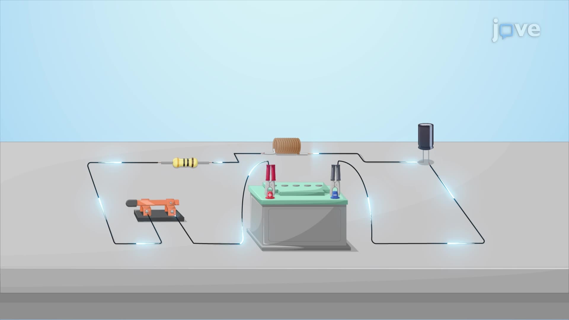
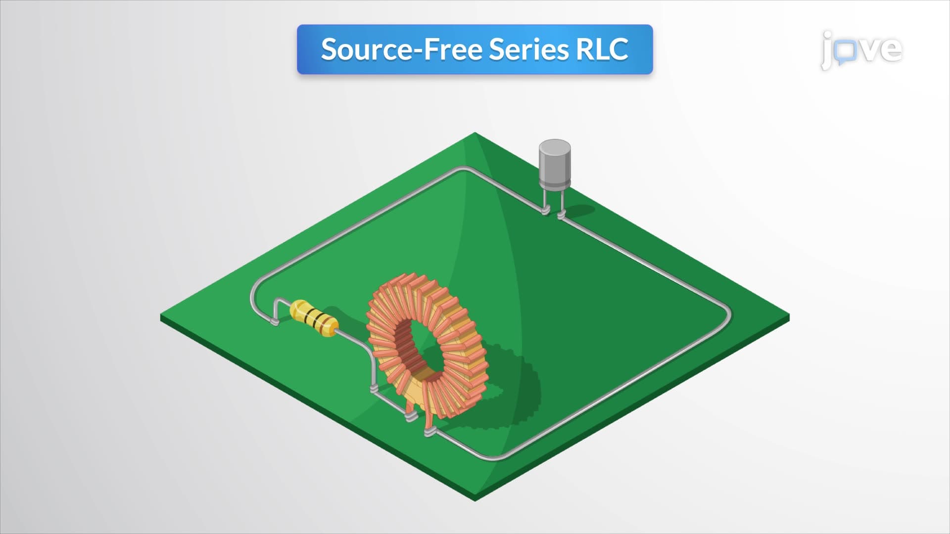
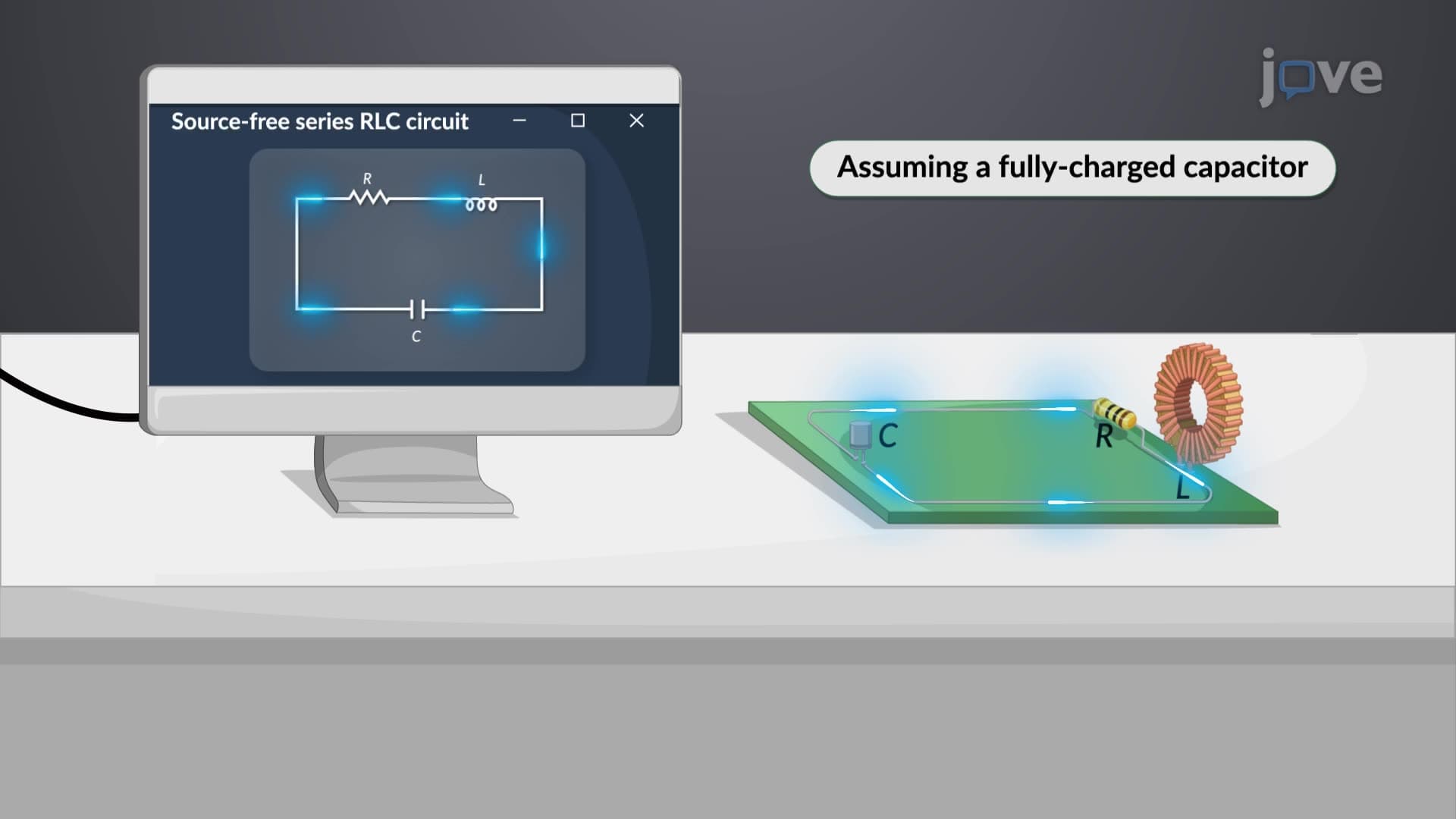
A Series RLC Circuit represents one of the most important configurations in electrical engineering, where a resistor (R), inductor (L), and capacitor (C) are connected in a single closed loop. Unlike parallel RLC circuits where components share common voltage points, series circuits force the same current through each element, creating unique behavioral characteristics essential for understanding complex electrical systems.
The circuit's behavior follows Kirchhoff's voltage law, producing a second-order linear differential equation: L(d²i/dt²) + R(di/dt) + i/C = dV/dt. This mathematical foundation appears frequently in AP Physics C examinations and college-level electrical engineering courses. Students preparing for the MCAT will encounter similar differential equations in physics sections, making mastery of this concept crucial for pre-med students.
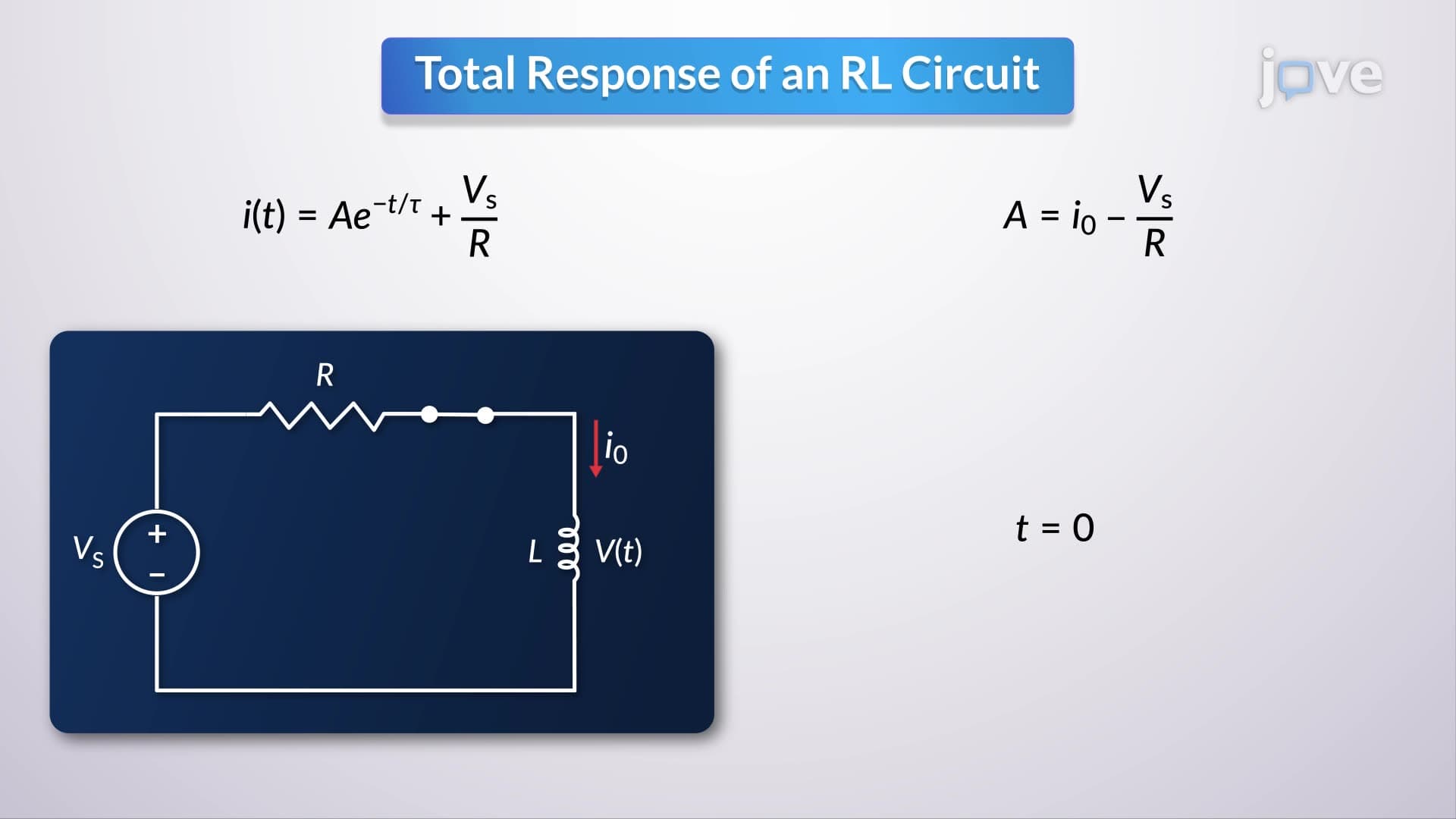
The complete solution combines transient and steady-state responses. The transient component represents temporary behavior that decays over time, while steady-state describes the circuit's final equilibrium condition. This dual-nature response mirrors concepts tested in SAT Subject Tests and forms the backbone of more advanced circuit analysis techniques.
Series RLC circuits find extensive application in American automotive systems. Ford's EcoBoost engines utilize RLC circuits for precise ignition timing, while Tesla's charging systems employ these principles for efficient power conversion. Radio stations across the United States rely on RLC tuning circuits to select specific broadcast frequencies, demonstrating the concept's relevance in telecommunications infrastructure.
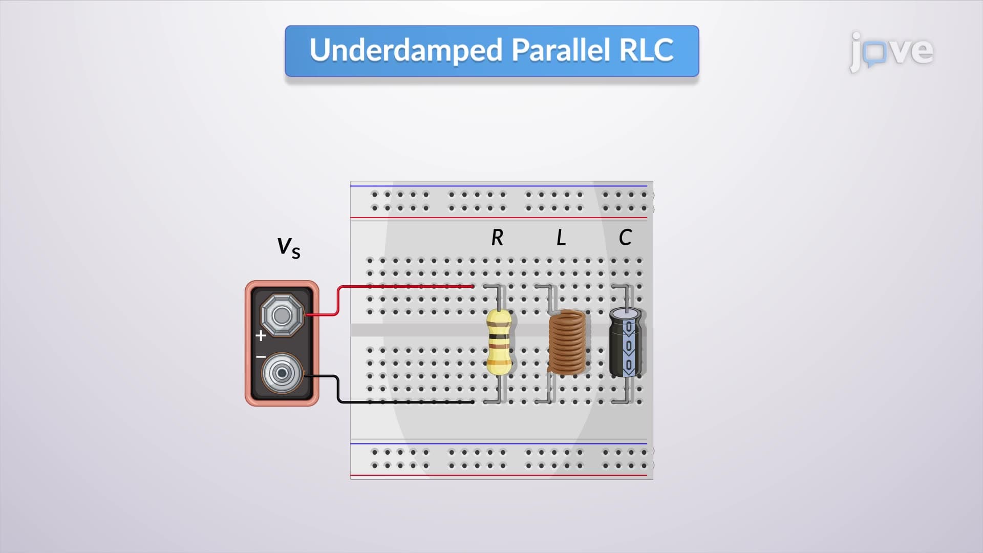
The circuit exhibits three distinct damping behaviors based on component values. Overdamped systems (high resistance) approach steady-state slowly without oscillation, commonly found in automotive shock absorber systems. Critically damped circuits reach equilibrium fastest without overshoot, preferred in precision instrumentation used by companies like Texas Instruments. Underdamped systems oscillate before settling, utilized in applications requiring resonant behavior like MRI machines in American hospitals.
Understanding these damping characteristics proves essential for engineering students at institutions like MIT, Stanford, and UC Berkeley, where circuit analysis forms the foundation of electrical engineering curricula.
Related Micro-courses