Loading video…


 9 Concepts
 5.2K views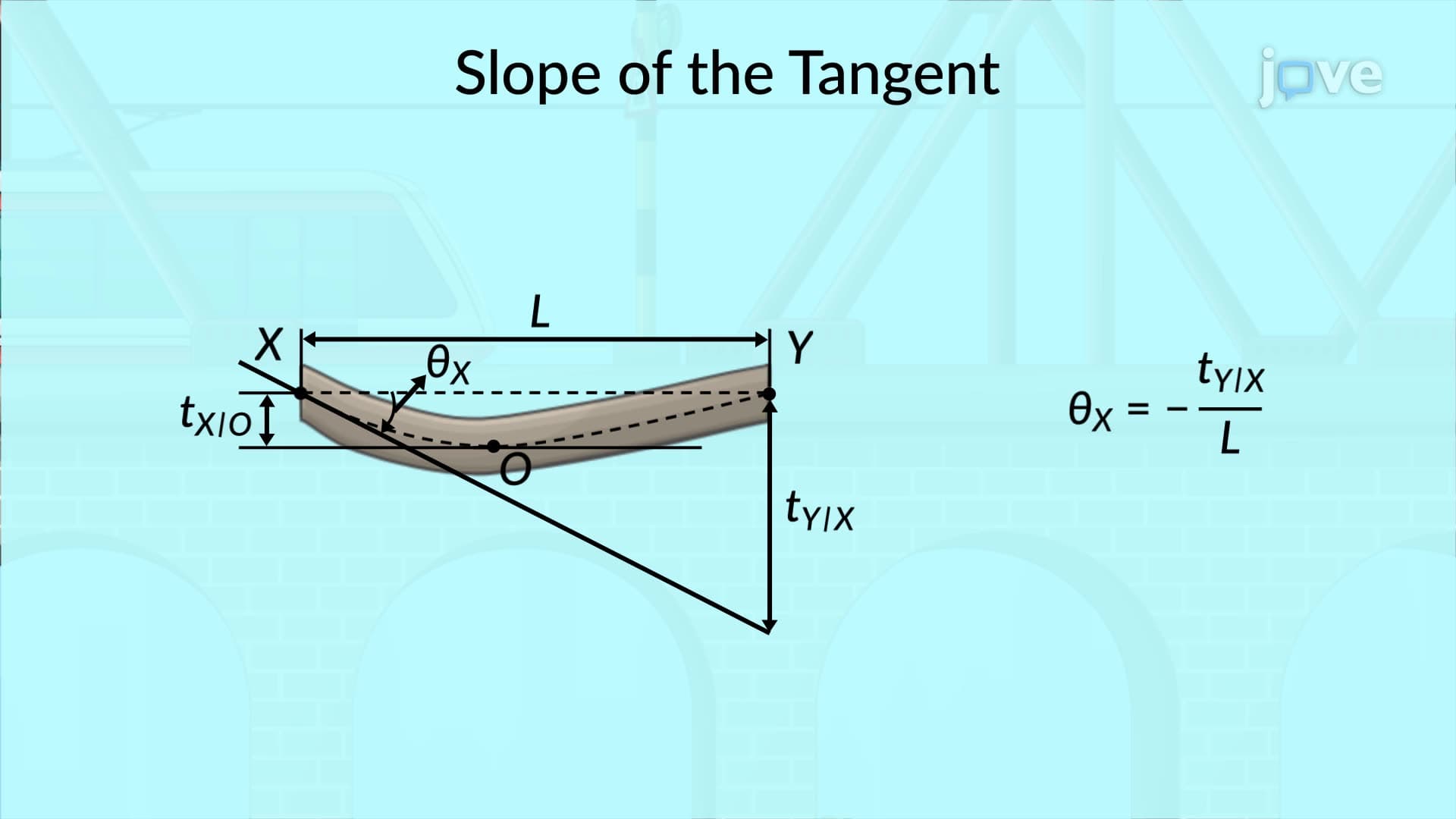

Video Summary: What Is Maximum Deflection
Ever wondered why engineers inspect the Golden Gate Bridge's center span more frequently than other sections? Maximum deflection determines the point where a beam bends the most under load, and it's rarely where you'd expect. Unlike symmetrical loading where deflection peaks at the center, unsymmetrical loads create maximum deflection at unexpected locations along the beam. Engineers use the moment-area theorem to precisely locate this critical point by finding where the beam's tangent becomes horizontal. Watch the full video on JoVE Coach to master this concept with expert-led visuals and step-by-step explanations.
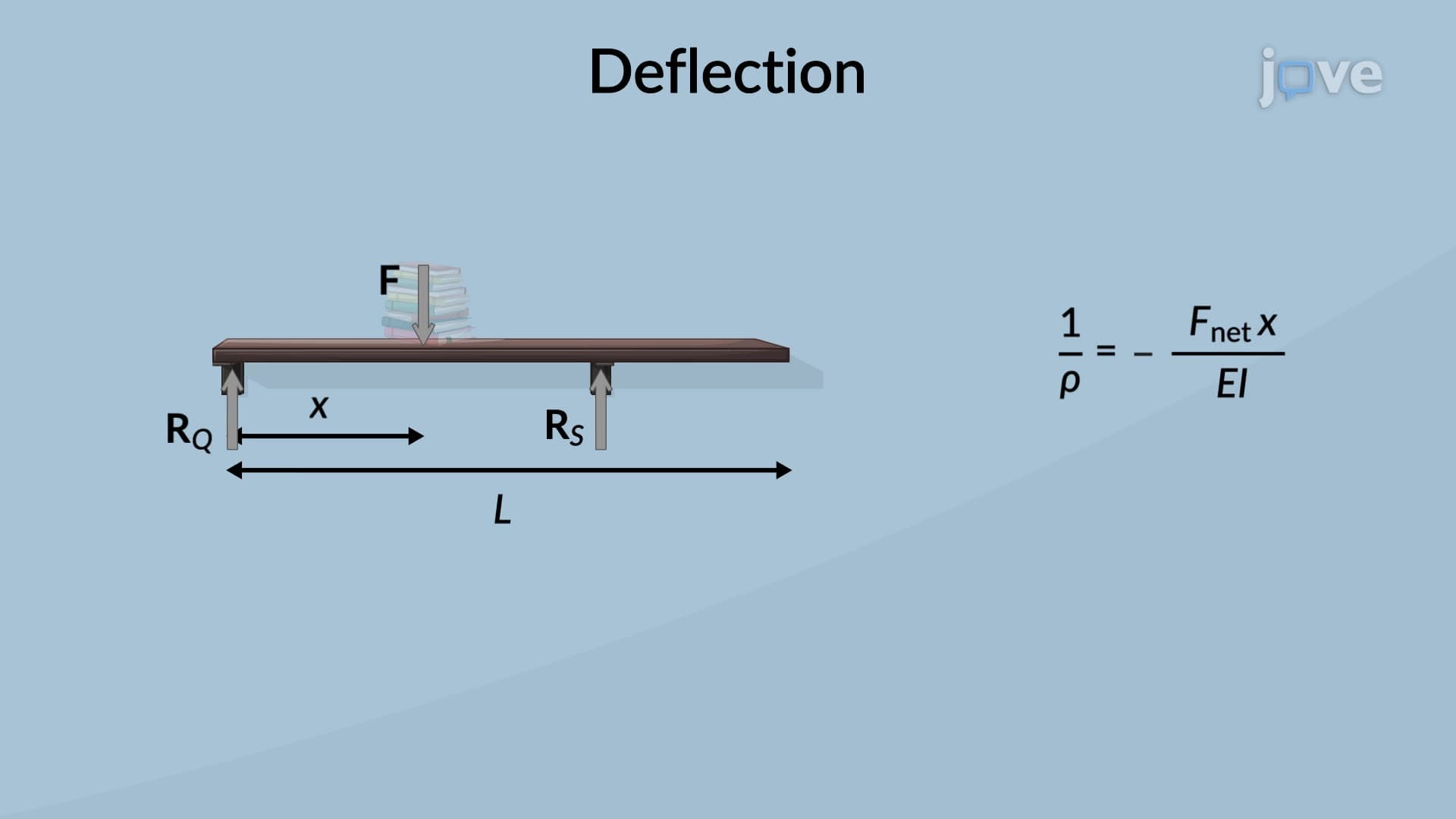
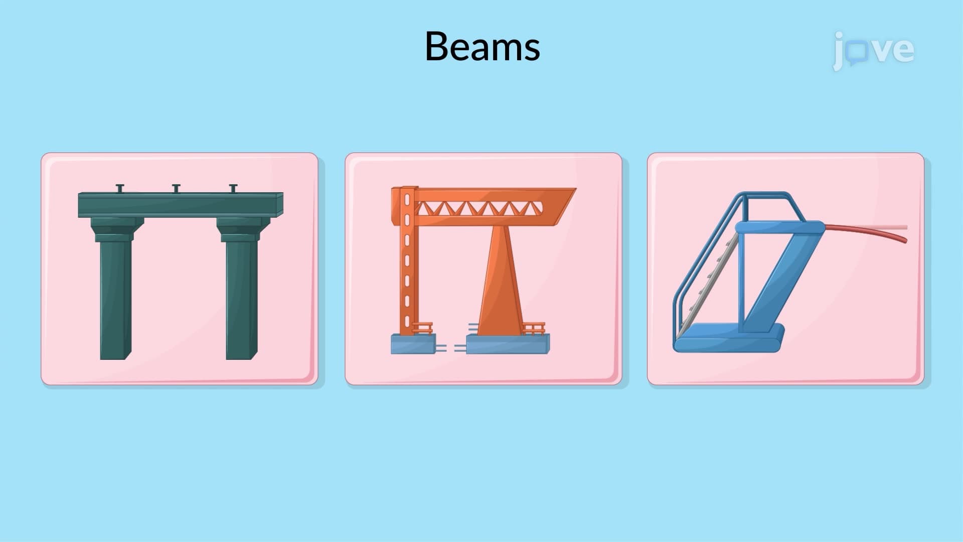
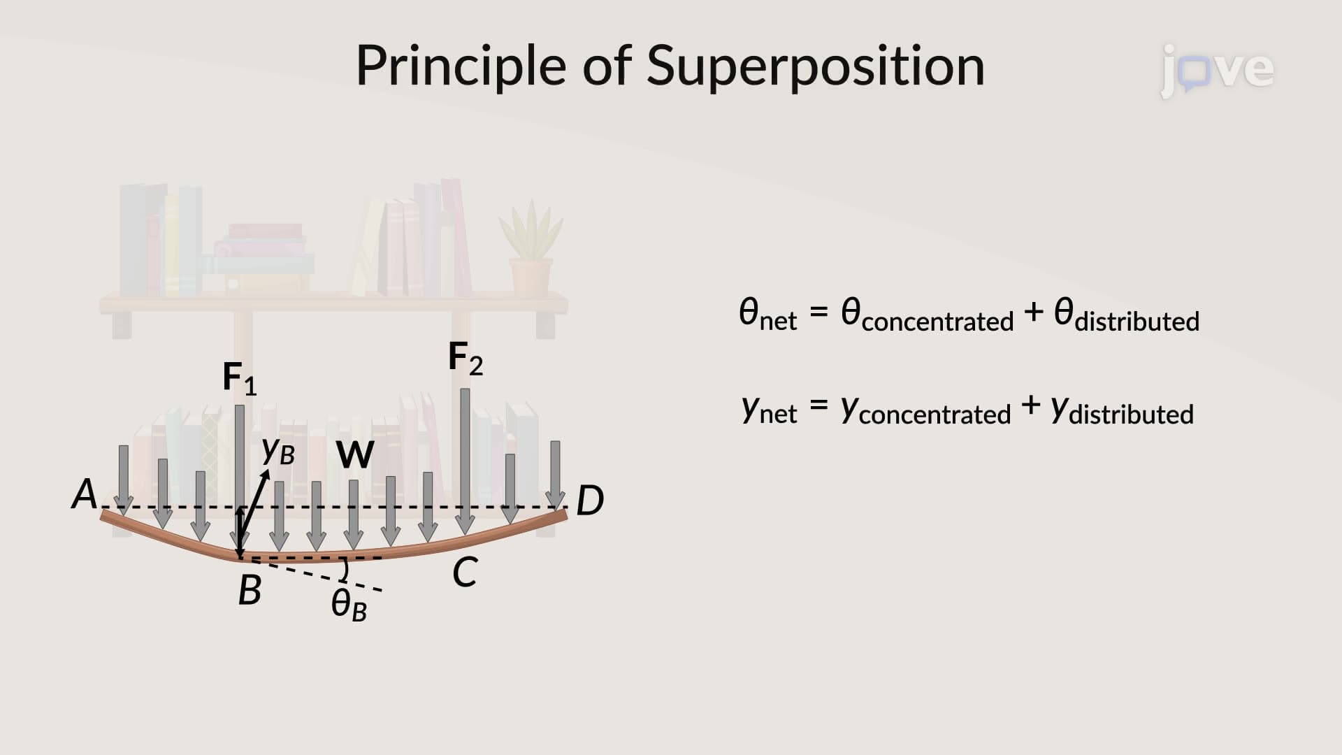
Maximum deflection represents the greatest vertical displacement that occurs anywhere along a loaded beam or structural member. This critical engineering parameter determines structural safety, performance limits, and design adequacy. Unlike intuitive assumptions, maximum deflection doesn't always occur at a beam's center-especially under unsymmetrical loading conditions common in real-world applications like highway overpasses, crane systems, and building frameworks.
The key to finding maximum deflection lies in identifying where the beam's slope equals zero-the point where the tangent line becomes perfectly horizontal. At this critical location, the beam transitions from bending downward to bending upward (or vice versa), creating the peak deflection point. Engineers use calculus-based methods and the moment-area theorem to mathematically pinpoint this location with precision.
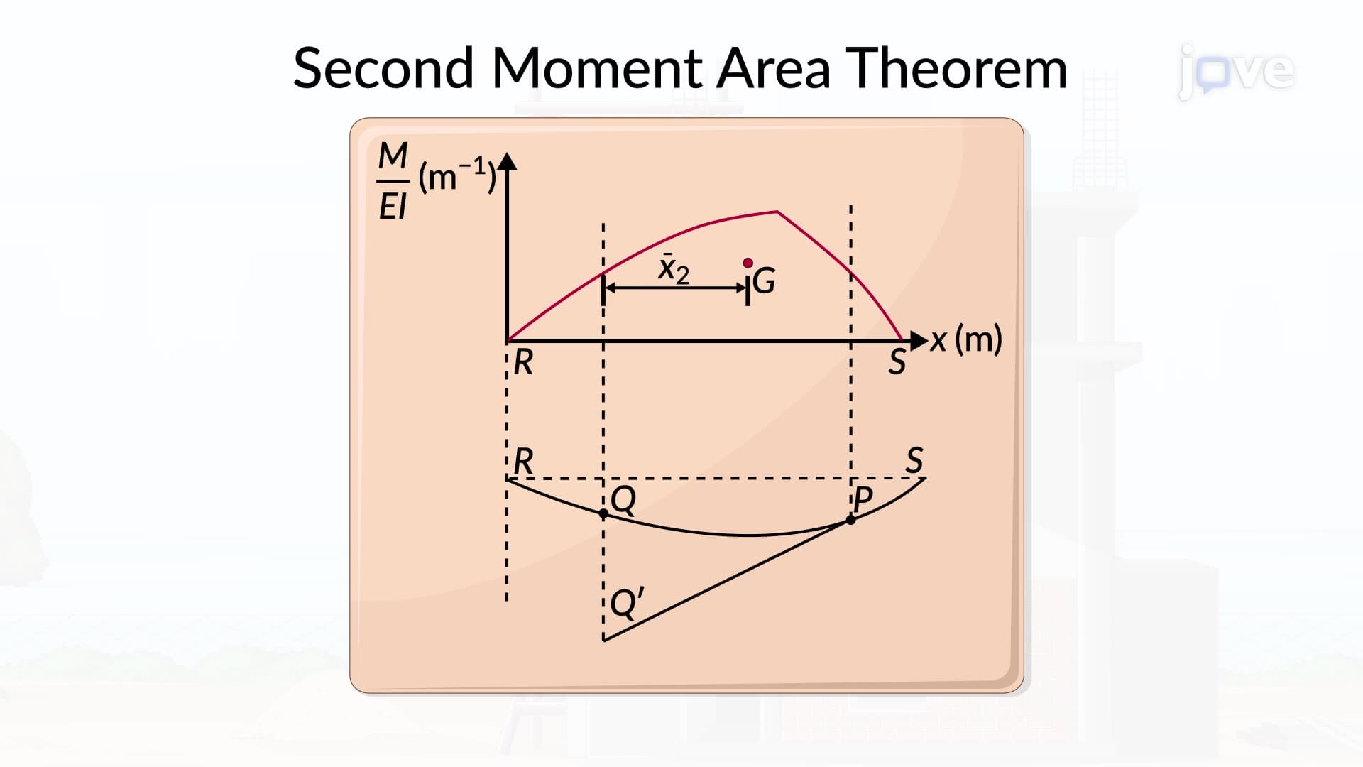
For unsymmetrical loads, this process involves calculating the tangential deviation between support points and analyzing the moment diagram. The first moment-area theorem provides the mathematical framework: the change in slope between two points equals the area under the M/EI (moment over flexural rigidity) curve between those points.
Consider the Chesapeake Bay Bridge in Maryland, where traffic loads create unsymmetrical loading patterns. Engineers must calculate maximum deflection under various scenarios: rush-hour traffic concentrated on one side, heavy truck convoys, and wind-induced lateral forces. These calculations ensure the bridge remains within acceptable deflection limits while maintaining structural integrity and user comfort.
In building design, maximum deflection calculations appear frequently in floor beam analysis. The International Building Code specifies deflection limits (typically L/360 for live loads) that structural engineers must verify through maximum deflection calculations. AP Physics C and college-level statics courses extensively cover these principles, while professional engineering exams test practical application skills.
The mathematical approach involves three key steps: first, determine the slope at each support using the moment-area method; second, locate the zero-slope point through geometric relationships; third, calculate the tangential deviation at this critical point. This systematic approach applies whether analyzing simply supported beams, cantilevers, or continuous beam systems common in modern construction.
Related Micro-courses