Loading subject page…

- Mechanical Engineering
- Torsion
- Circular Shaft - Stresses in Linear Range
Micro-course: Torsion
5,181 views
Learn key concepts and earn your certificate.

Circular Shaft - Stresses in Linear Range

00:00
01:13
Video Summary: What are Circular Shaft Stresses
Ever wondered why drive shafts in Ford F-150 trucks can transfer massive engine torque without snapping? Circular shaft stresses determine exactly how much twisting force these rotating components can handle before failure. When torque is applied within Hooke's law limits, engineers use the elastic torsion formula to calculate shearing stresses throughout solid and hollow circular shafts, ensuring safe operation in everything from automotive drivetrains to industrial machinery. Watch the full video on JoVE Coach to master this concept with expert-led visuals and step-by-step explanations.
- Understand what are circular shaft stresses and how they develop when torque is applied to rotating mechanical components
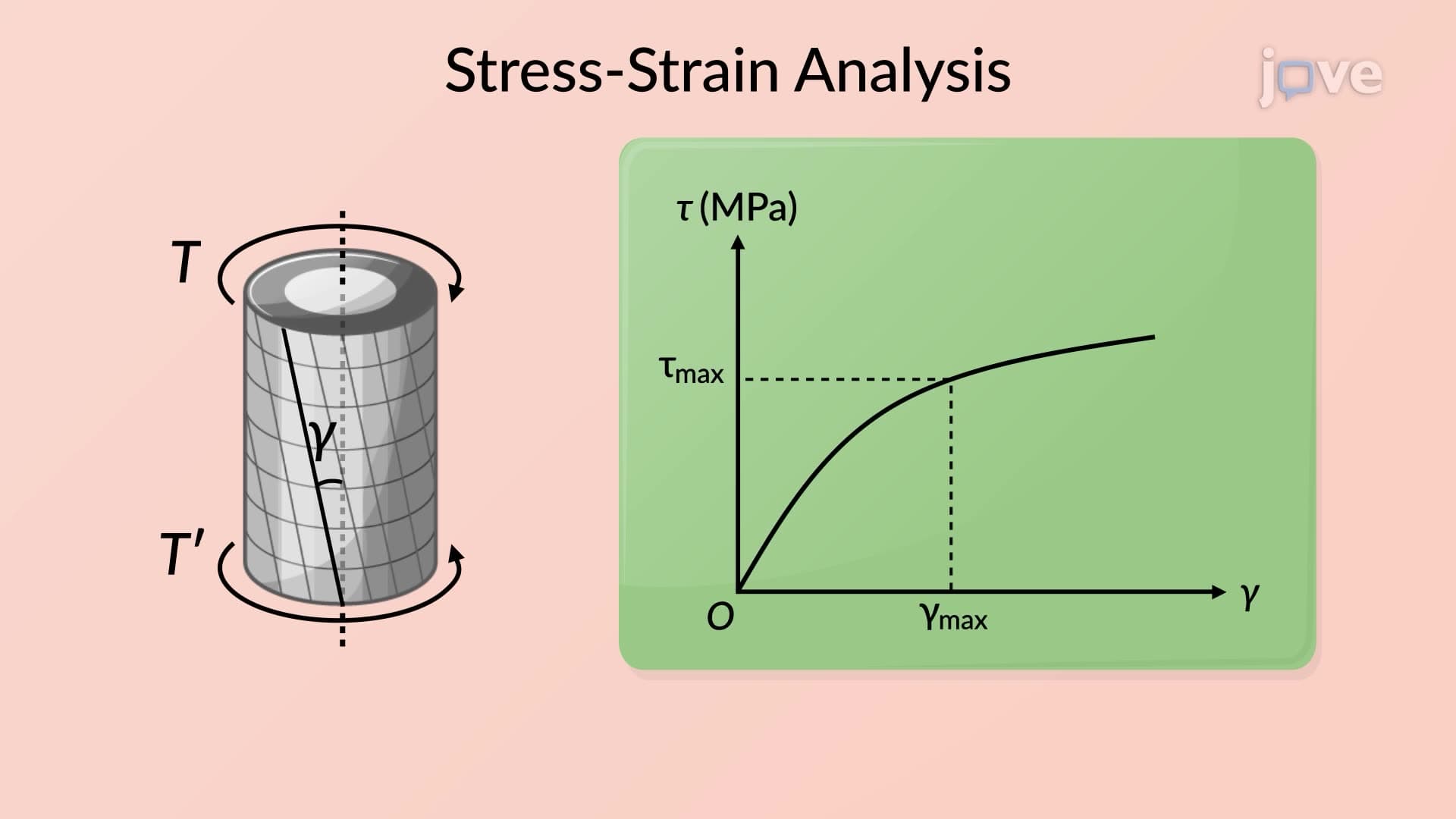
- Identify the relationship between shearing strain, modulus of rigidity, and Hooke's Law in circular shaft analysis
- Analyze the elastic torsion formula and its application to both solid and hollow circular shafts
- Apply polar moment of inertia calculations for different shaft geometries and cross-sectional properties
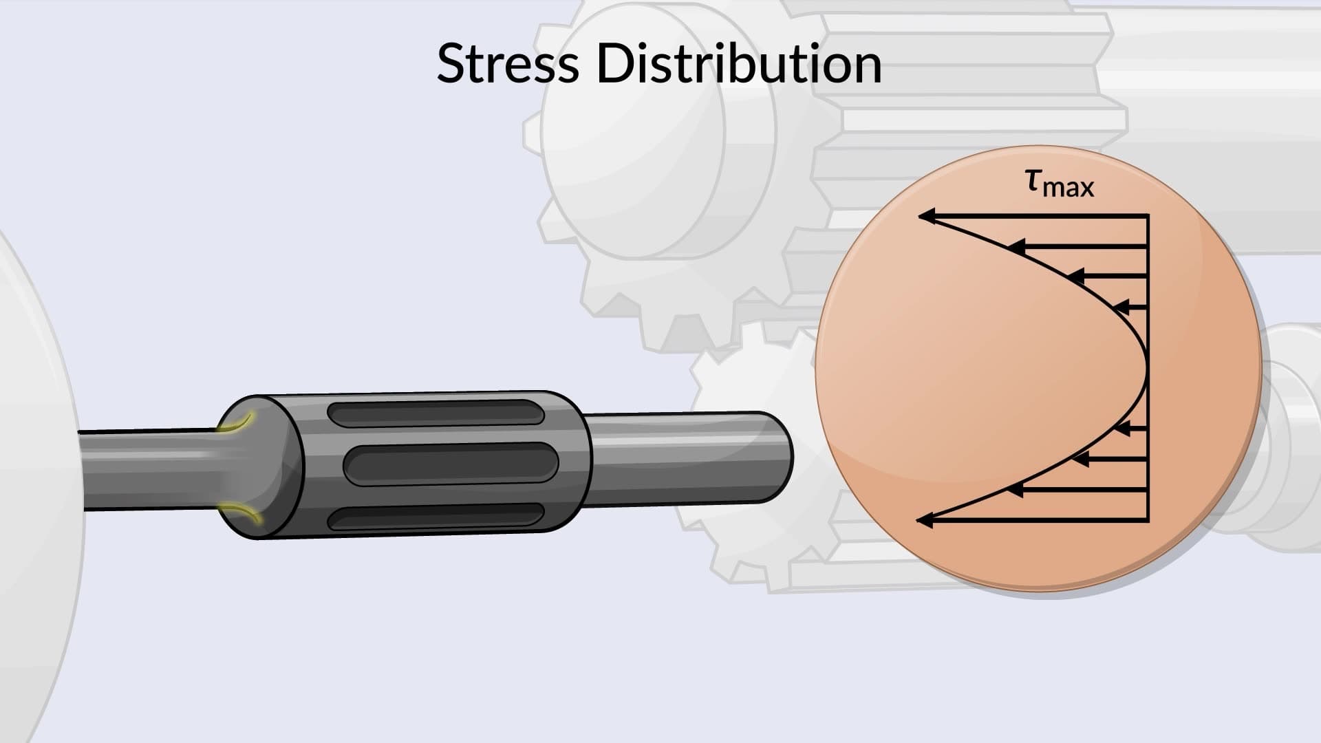
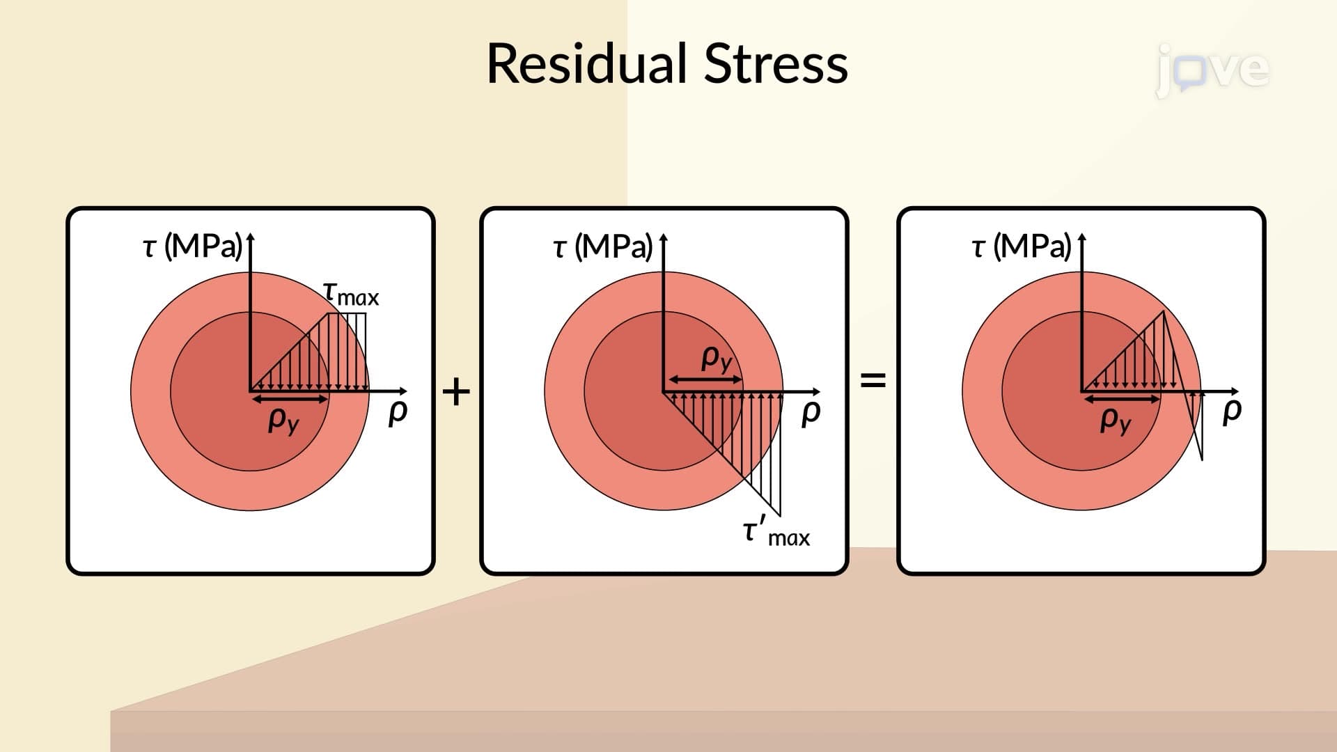
- Evaluate maximum shearing stress distributions across circular shaft cross-sections under torsional loading
- Compare stress behavior in solid versus hollow shafts using appropriate mathematical expressions
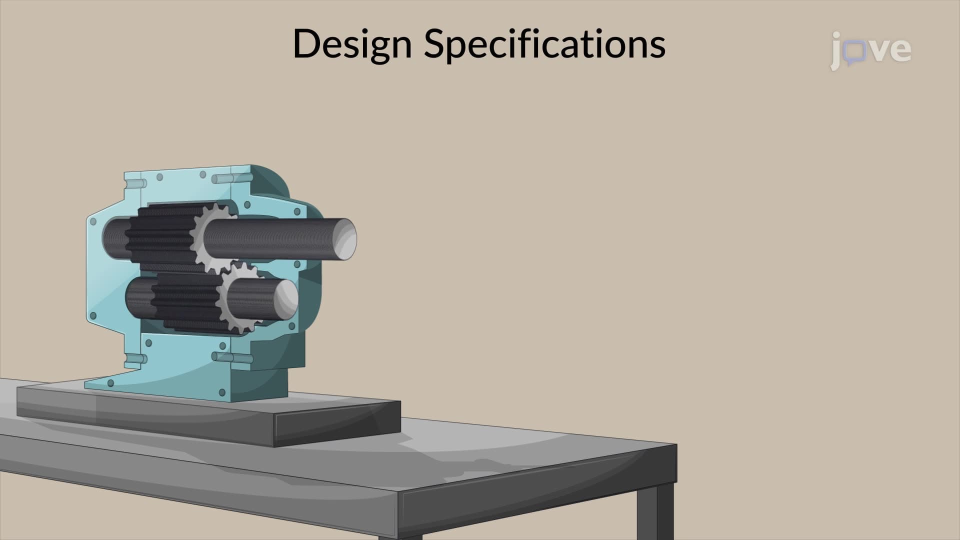
- Recognize real-world applications of circular shaft stress analysis in automotive, aerospace, and manufacturing industries
- Explore the fundamental assumptions and limitations of elastic torsion theory in engineering design
Understanding Circular Shaft Stresses Fundamentals
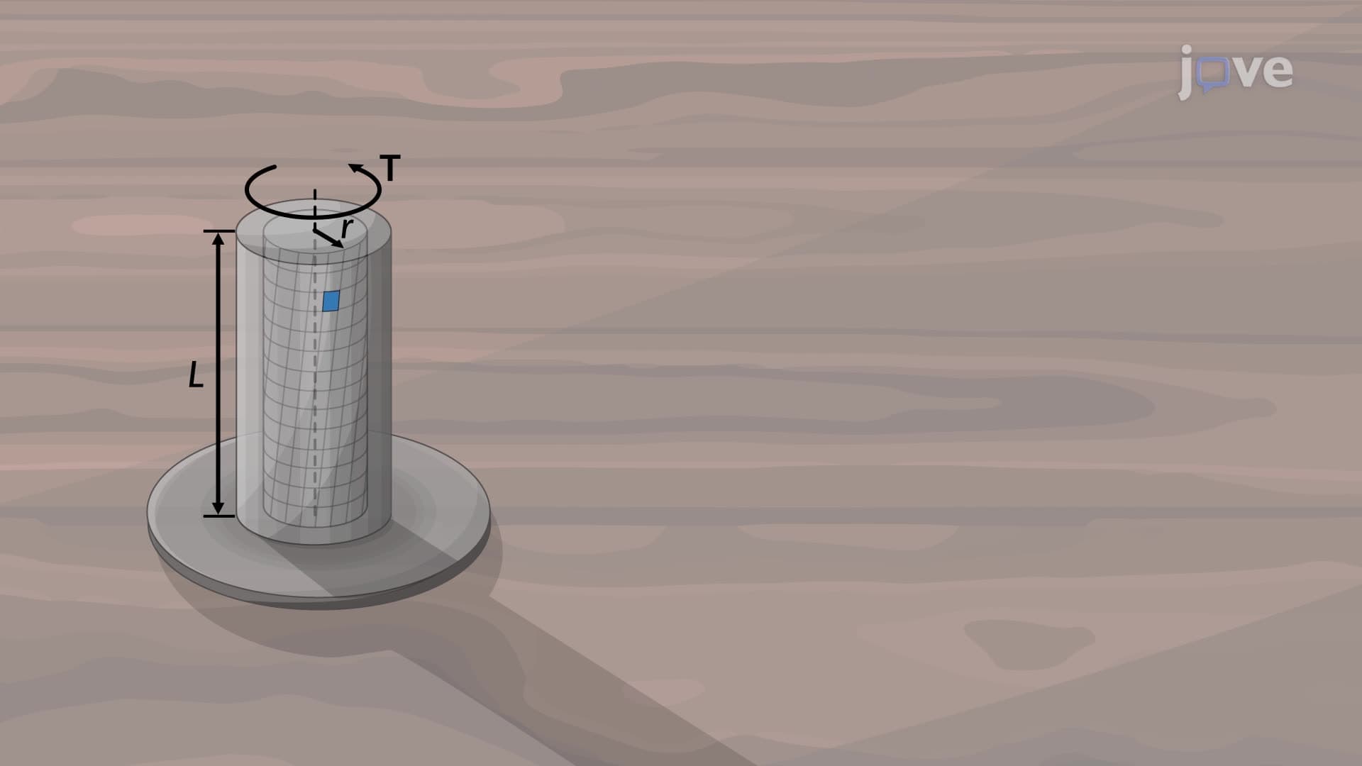
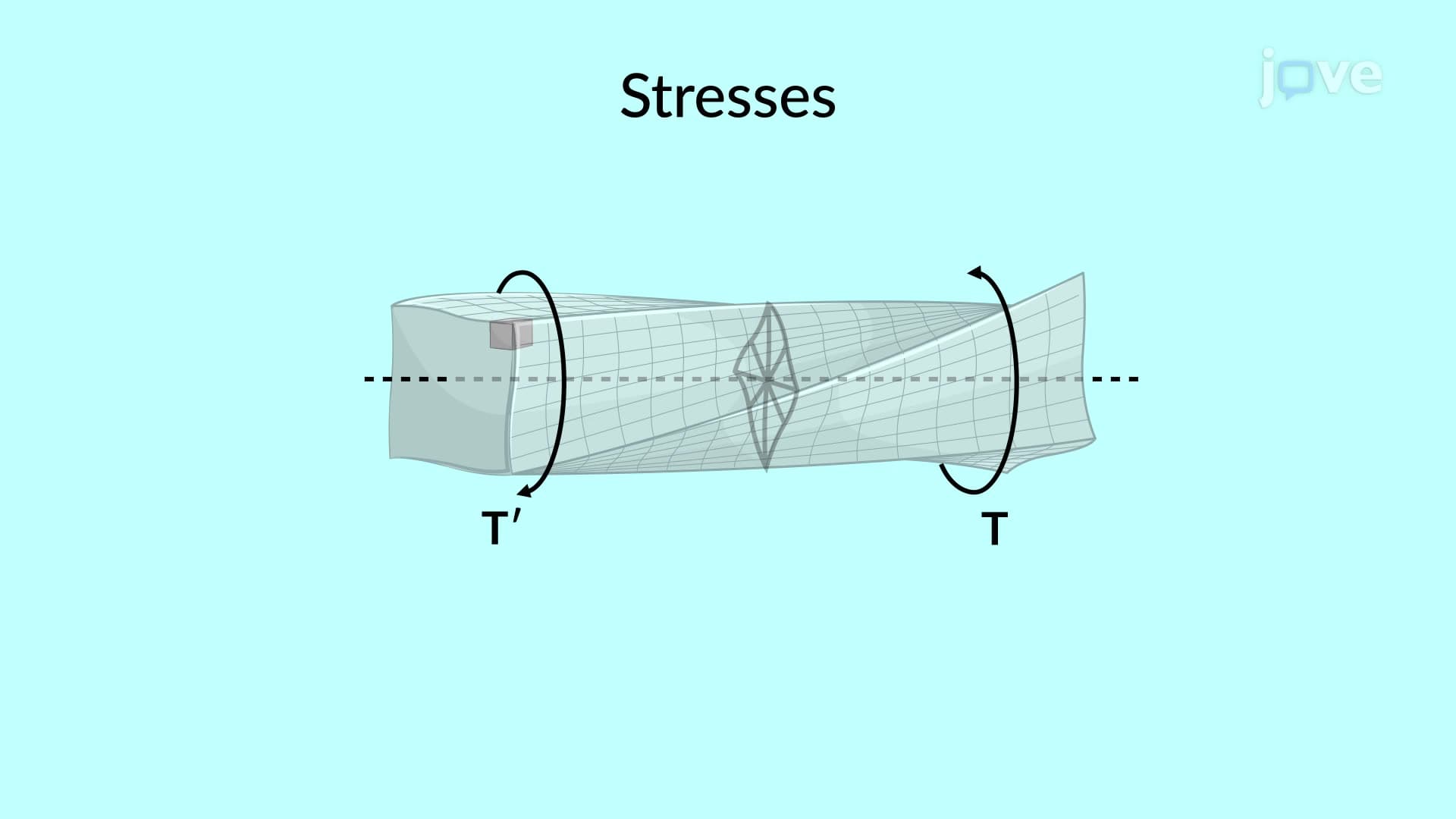
Circular shaft stresses represent the internal forces that develop when rotating mechanical components experience twisting loads, or torque. These stresses are critical in designing everything from bicycle pedal cranks to massive wind turbine drive shafts. When you turn a wrench or start your car's engine, circular shafts throughout these systems experience torsional loading that creates predictable stress patterns engineers must understand and control.
The foundation of circular shaft stress analysis lies in the elastic behavior of materials. Within Hooke's law limits, materials deform proportionally to applied loads and return to their original shape when loads are removed. This elastic relationship allows engineers to develop precise mathematical models for predicting shaft performance under various operating conditions.
The Elastic Torsion Formula and Its Applications
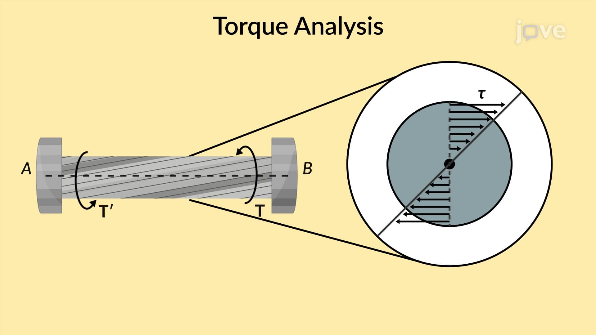
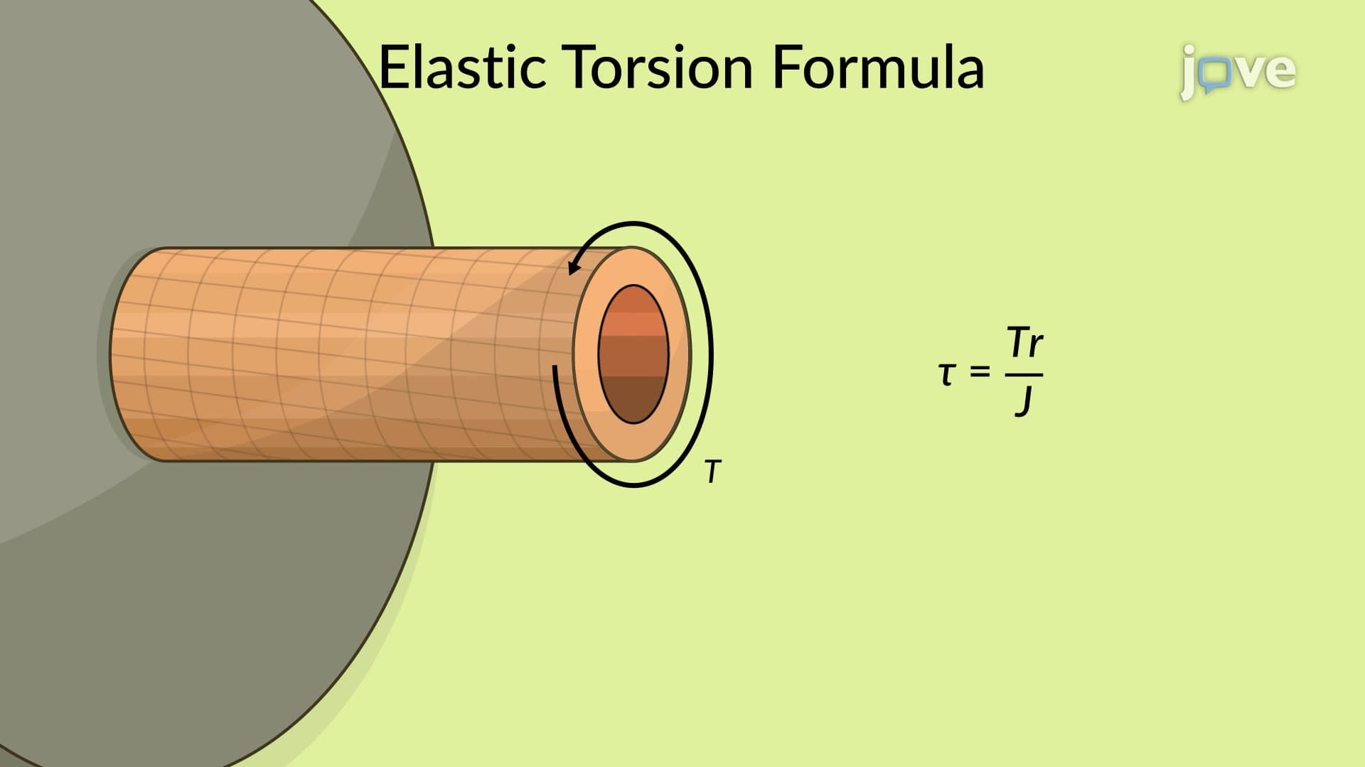
The elastic torsion formula serves as the cornerstone equation for circular shaft stress calculations: τ = (T × r) / J, where τ represents shearing stress, T is applied torque, r is the radial distance from the shaft center, and J is the polar moment of inertia. This formula reveals that stress varies linearly from zero at the shaft center to maximum values at the outer surface.
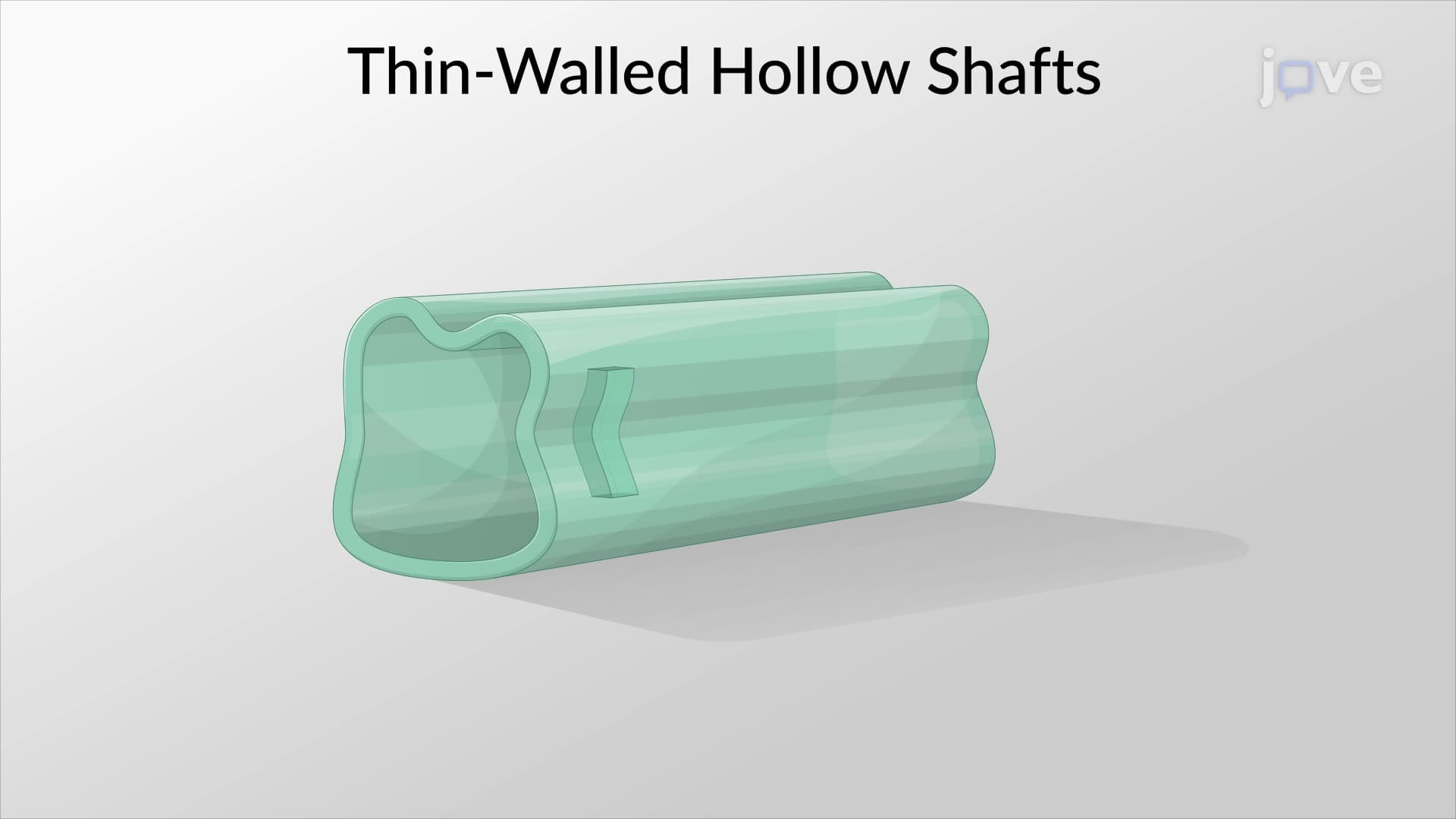
For solid circular shafts, the polar moment of inertia equals J = π × d^4 / 32, where d is the shaft diameter. However, hollow shafts use J = π × (d_outer^4 - d_inner^4) / 32, accounting for the material removed from the center. This difference explains why hollow shafts like those in Boeing 787 aircraft structures provide excellent strength-to-weight ratios compared to solid alternatives.
Real-World Engineering Applications
Circular shaft stress analysis directly impacts numerous US industries and applications. Automotive driveshafts in Chevrolet Corvettes must handle over 600 lb-ft of torque while maintaining safety factors that prevent catastrophic failure. Similarly, oil drilling equipment used in Texas and North Dakota requires massive drive shafts capable of withstanding extreme torsional loads thousands of feet underground.
Students preparing for AP Physics C exams or college-level mechanics courses frequently encounter circular shaft problems that test understanding of stress distributions, material properties, and failure criteria. These concepts also appear in engineering licensure examinations and graduate-level coursework across mechanical, civil, and aerospace engineering programs.
Advanced Considerations and Design Factors
Professional engineers must consider additional factors beyond basic stress calculations when designing circular shafts. These include fatigue life under cyclic loading, stress concentrations at geometric discontinuities, and temperature effects on material properties. Manufacturing processes like heat treatment and surface finishing also significantly influence shaft performance in critical applications such as jet engine components and precision medical devices.
Frequently Asked Questions
Circular shaft stresses are internal forces that develop when rotating cylindrical components experience twisting loads or torque. They're crucial because they determine whether shafts in cars, machinery, and structures can safely handle operational loads without breaking. Understanding these stresses helps engineers design everything from bicycle chains to massive industrial equipment that operates reliably under demanding conditions.
Focus on shearing stresses caused by torsional loading, which follow the elastic torsion formula τ = (T × r) / J. You'll need to understand how stress varies linearly across the shaft radius, reaching maximum values at the outer surface. Practice problems involving both solid and hollow circular shafts, as these commonly appear on AP Physics C mechanics exams and college engineering assessments.
These concepts typically appear in physics sections testing mechanics and materials science knowledge. Expect questions about stress-strain relationships, torque calculations, and basic strength of materials principles. Focus on understanding the physical meaning behind equations rather than memorizing complex formulas, as exams often test conceptual understanding through multiple-choice scenarios.
Every time you drive a car, the driveshaft connecting your transmission to the wheels experiences circular shaft stresses. Bicycle pedal cranks, motorcycle drive chains, and even the rotating mechanisms in washing machines all rely on circular shaft stress principles. Wind turbines across states like Texas and Iowa use massive drive shafts designed using these exact engineering calculations.
Basic algebra and introductory calculus provide sufficient mathematical background for most circular shaft stress problems. The core concepts build on fundamental physics principles you've likely encountered in high school mechanics courses. While advanced applications require more sophisticated mathematics, mastering the fundamental relationships and physical intuition proves more valuable for most students.
Start by mastering the elastic torsion formula and understanding what each variable represents physically. Practice drawing stress distribution diagrams and work through problems involving both solid and hollow shafts. Create a formula sheet with polar moment of inertia expressions for different geometries, and always check your answers using dimensional analysis to catch common mistakes.
Build on this foundation by exploring beam bending stresses, combined loading scenarios, and failure theories like von Mises stress criteria. These concepts naturally extend circular shaft principles to more complex structural analysis problems encountered in mechanical and civil engineering coursework. Consider studying fatigue analysis and stress concentrations for advanced applications.
Related Micro-courses

18 Concepts
4 Concepts
