Loading subject page…


274,846 views

Video Summary: Drawing Free Body Diagrams Rules Guide
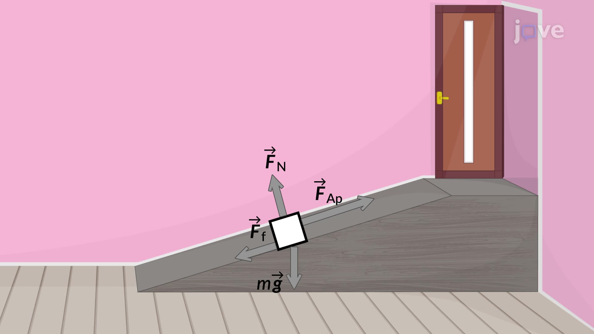
Ever wonder how NASA engineers calculate the forces needed to launch rockets, or how bridge designers ensure structures won't collapse? Drawing free body diagrams rules form the foundation of these calculations. When pushing a refrigerator up a ramp-a common scenario in American homes during moves-engineers use these same principles to determine required force and prevent tipping. This systematic approach to visualizing forces transforms complex real-world problems into manageable diagrams that reveal hidden relationships between gravitational, normal, friction, and applied forces. Watch the full video on JoVE Coach to master this concept with expert-led visuals and step-by-step explanations.
Drawing free body diagrams rules provide a systematic methodology for visualizing and analyzing forces in physics problems. These rules transform abstract force concepts into concrete visual representations that students can manipulate mathematically. The core principle involves isolating your system of interest-whether a sliding box, orbiting satellite, or suspended bridge cable-and representing only the forces acting upon it.
This isolation principle distinguishes professional physics analysis from intuitive thinking. When analyzing a car climbing a hill, we focus solely on forces acting ON the car (gravity, normal force from road, friction, engine thrust) while ignoring forces the car exerts ON other objects (pressure on road surface, exhaust gases). This systematic approach prevents the confusion that often derails beginning physics students.
The geometric representation follows strict conventions that ensure consistency across problems. Objects become simplified shapes-circles for particles, rectangles for extended bodies, or points when size doesn't matter. This abstraction allows focus on force relationships rather than irrelevant geometric details.
Force arrows must reflect both direction and relative magnitude. A 500-newton gravitational force requires a longer arrow than a 200-newton friction force. Arrow placement typically originates from the object's center of mass, though some textbooks show forces at their actual points of application. Students preparing for AP Physics or college mechanics courses should verify their instructor's preferred convention.
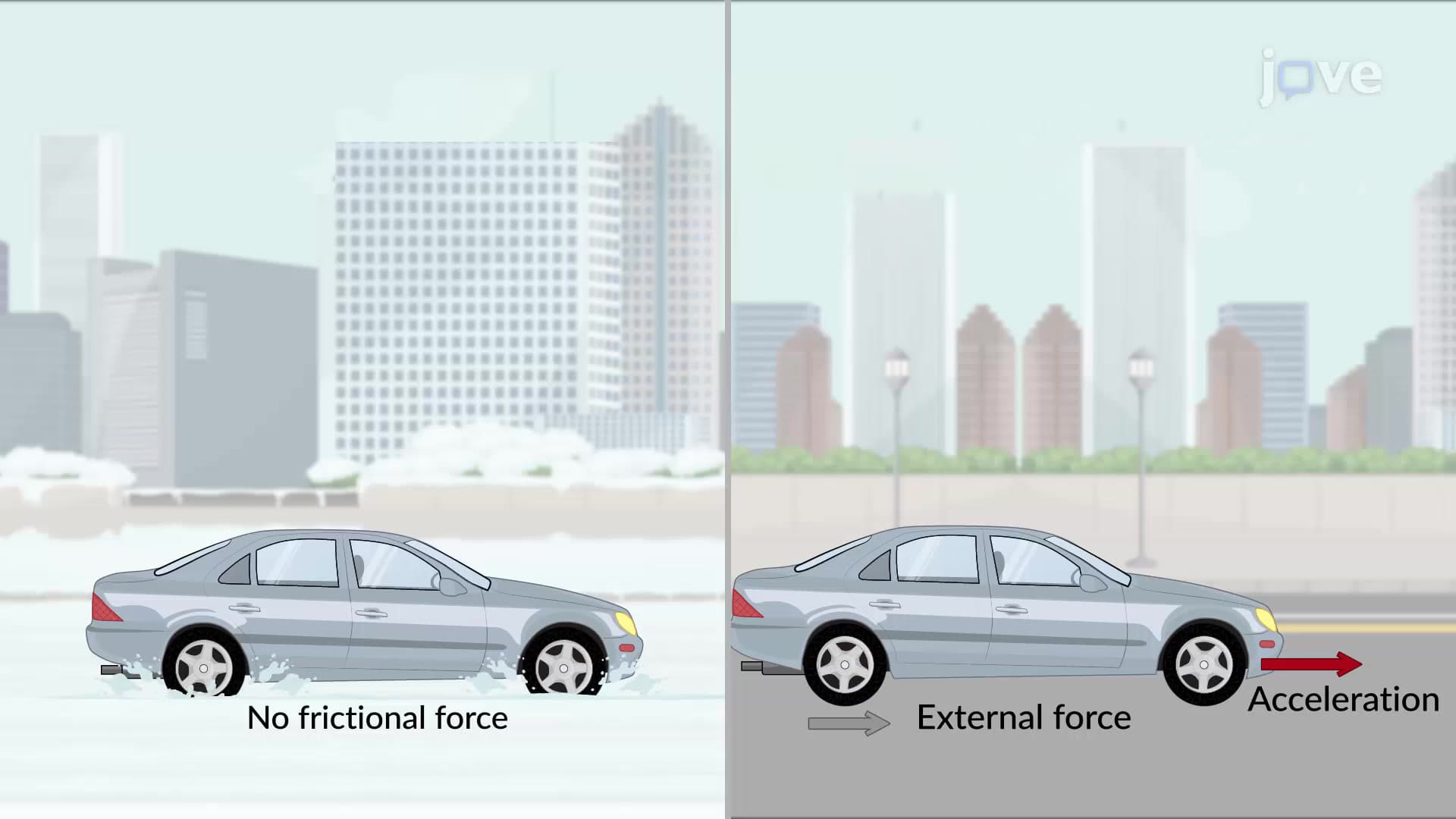
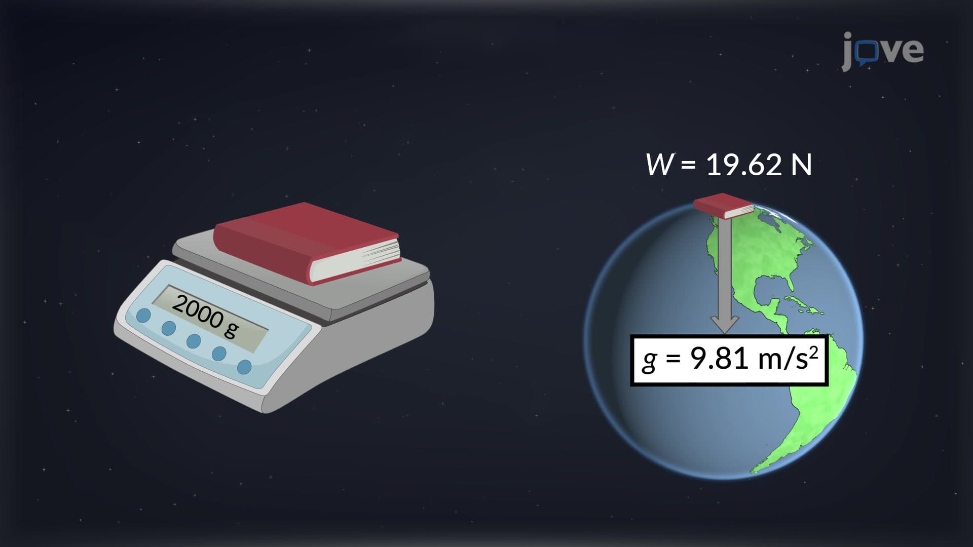
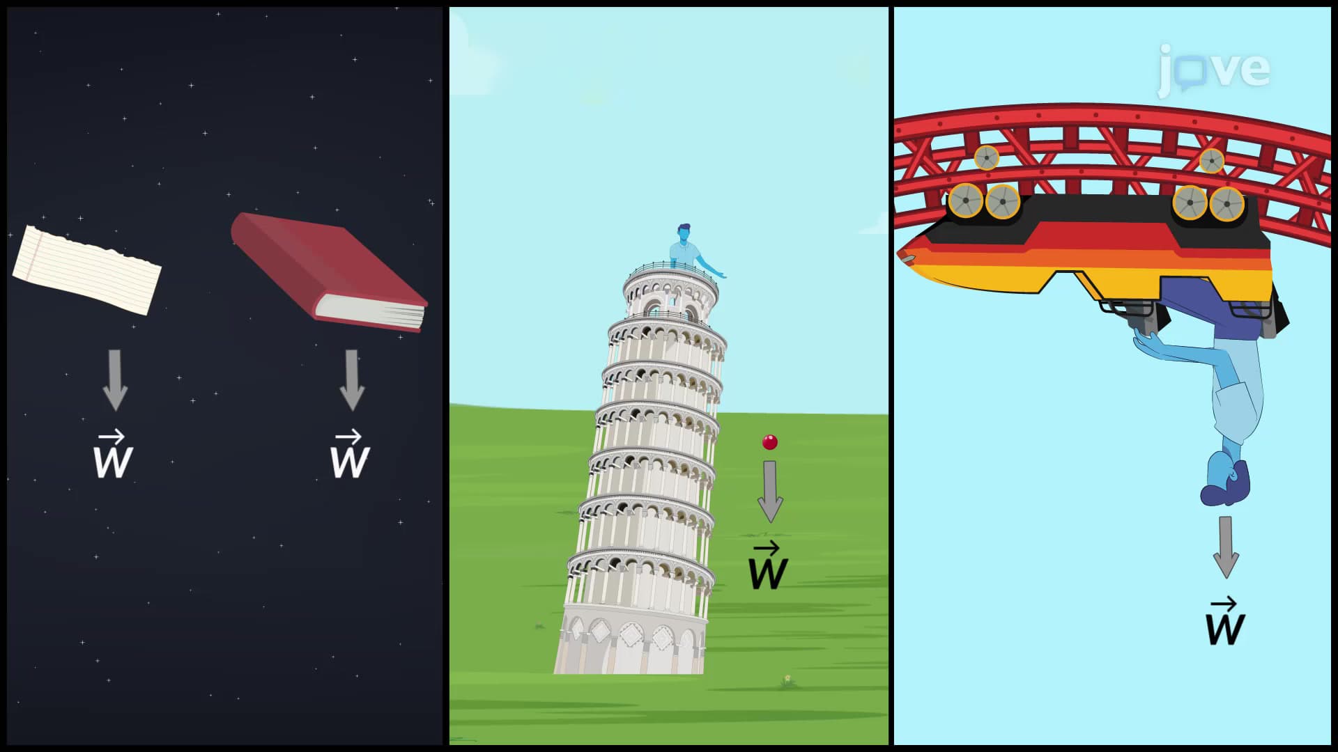
American engineering and physics education emphasizes four primary force categories. Gravitational forces always point toward Earth's center with magnitude F = mg. Normal forces act perpendicular to contact surfaces-crucial for analyzing everything from roller coasters to construction crane stability. Friction forces oppose relative motion, determining whether your car maintains traction on icy roads or whether packages slide in delivery trucks.
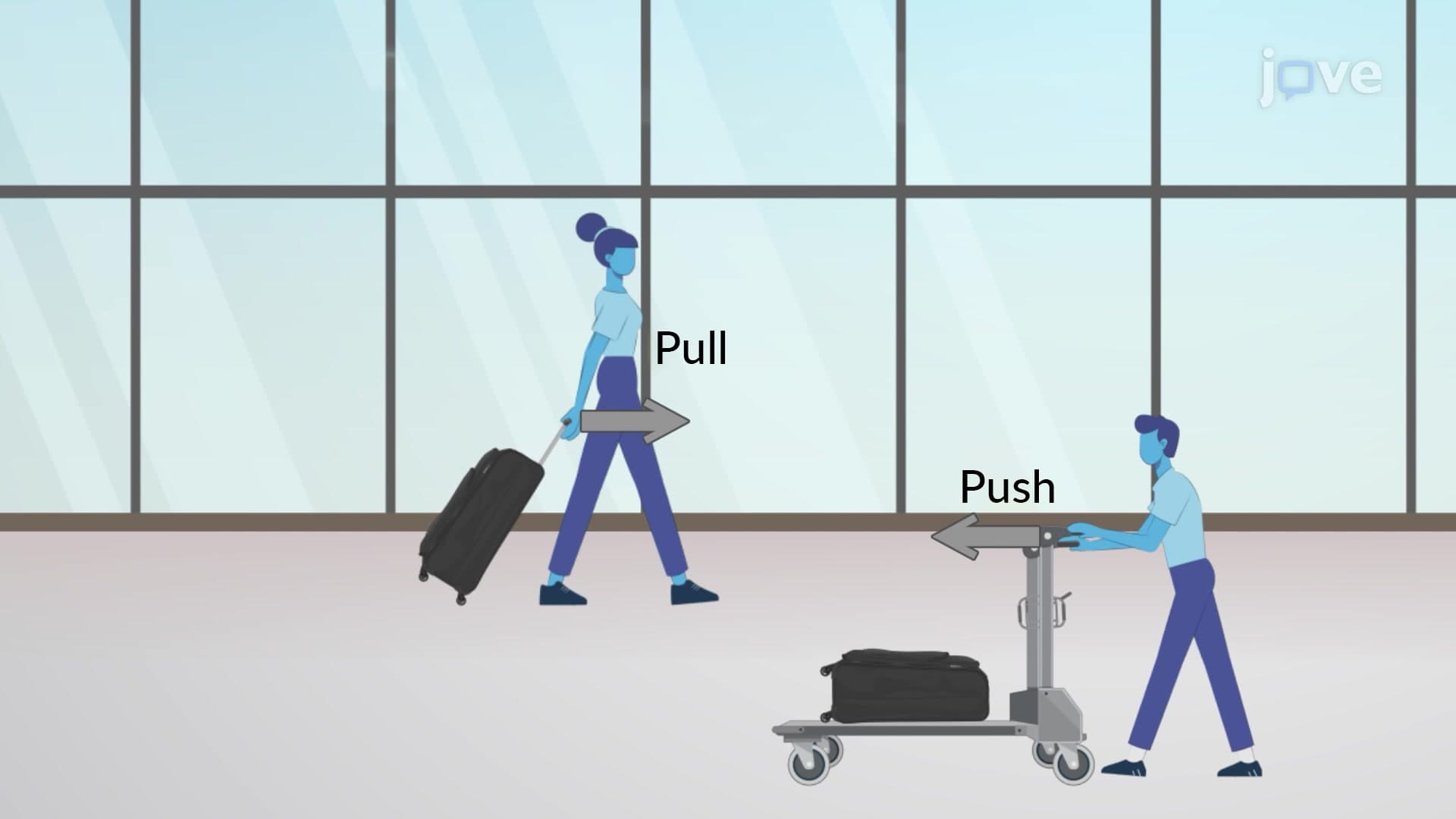
Applied forces represent human or mechanical inputs. When analyzing a construction worker pushing a wheelbarrow up a ramp, the applied force arrow shows both the push direction and required magnitude for equilibrium or acceleration. These scenarios appear frequently on standardized tests like the SAT Subject Test in Physics and college placement exams.
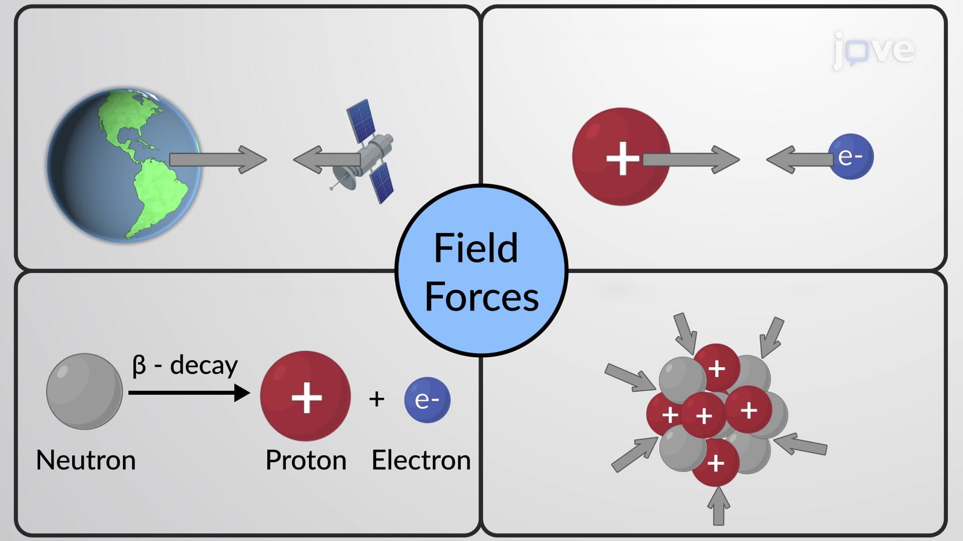
Successful force analysis requires systematic thinking that serves students throughout STEM careers. Begin by clearly defining your system boundaries-what object are you analyzing? Next, inventory all force sources: What touches your object? What fields (gravitational, electromagnetic) influence it? Finally, represent each force with proper direction and proportional magnitude.
This methodology proves invaluable beyond introductory physics. Biomedical engineers analyzing joint forces in prosthetic limbs, aerospace engineers calculating satellite trajectories, and civil engineers designing earthquake-resistant buildings all rely on these fundamental diagramming principles learned in high school and college physics courses.
Related Micro-courses