Loading video…


 11 Concepts
 5.6K views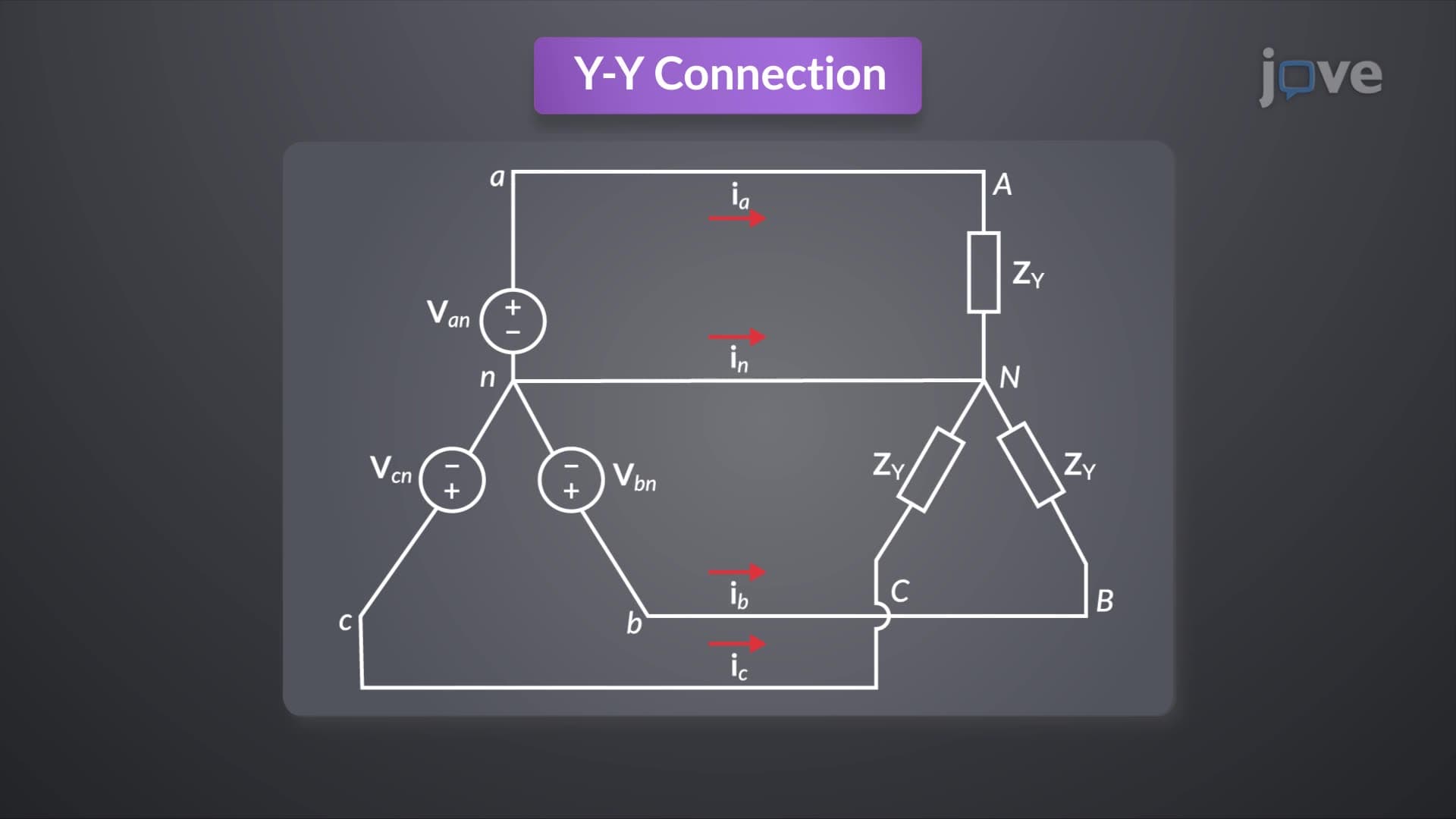

Video Summary: The Y to Y Circuit Explained
Ever wondered how the massive electrical grid powering Times Square in New York maintains perfect balance across three phases? The Y to Y circuit forms the backbone of most commercial electrical systems in the United States. This balanced four-wire configuration connects Y-shaped voltage sources to Y-shaped loads through a neutral wire, ensuring equal power distribution across all three phases. Understanding how line currents maintain 120-degree phase differences while the neutral current remains zero is crucial for electrical engineering success. Watch the full video on JoVE Coach to master this concept with expert-led visuals and step-by-step explanations.
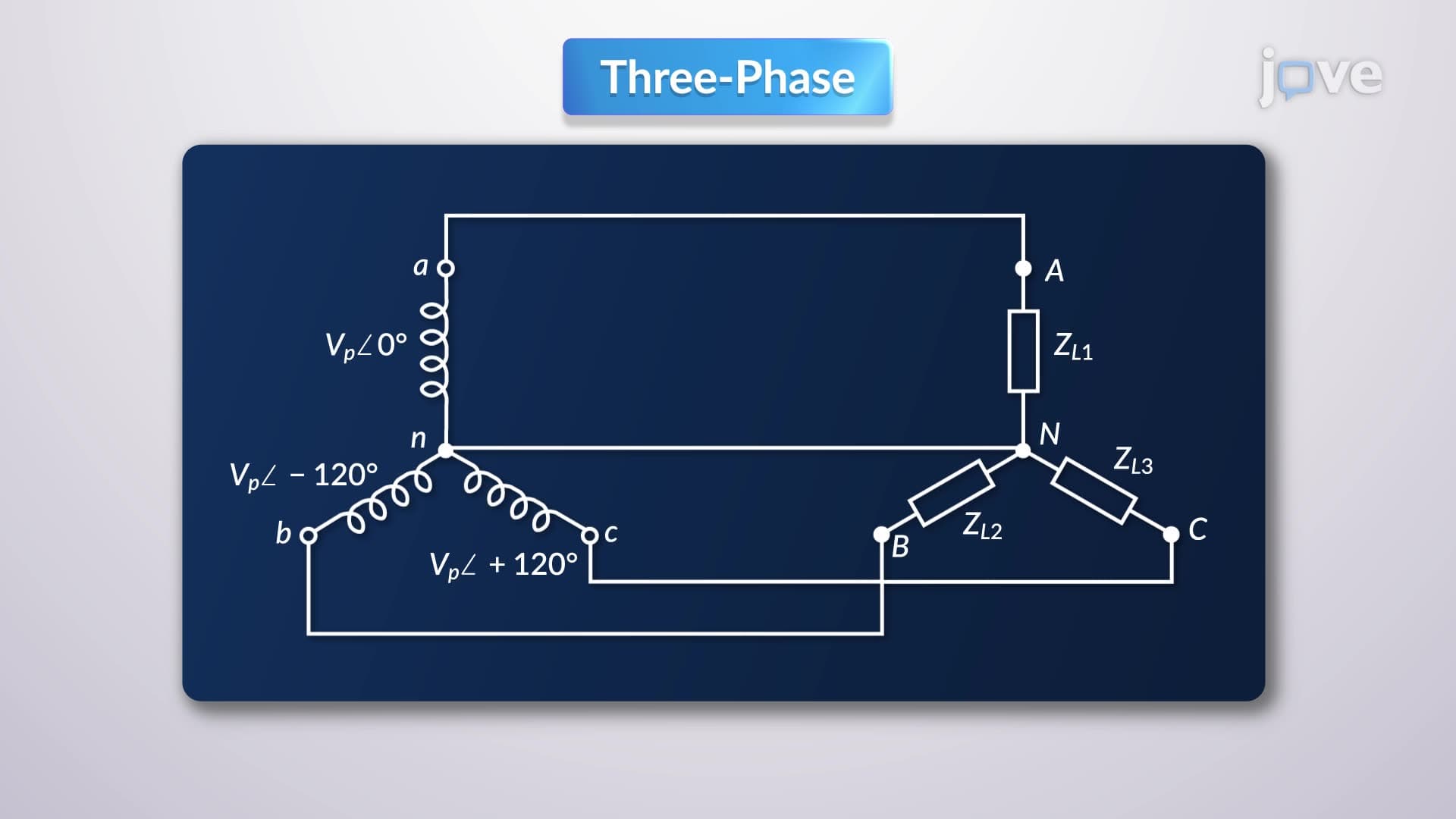
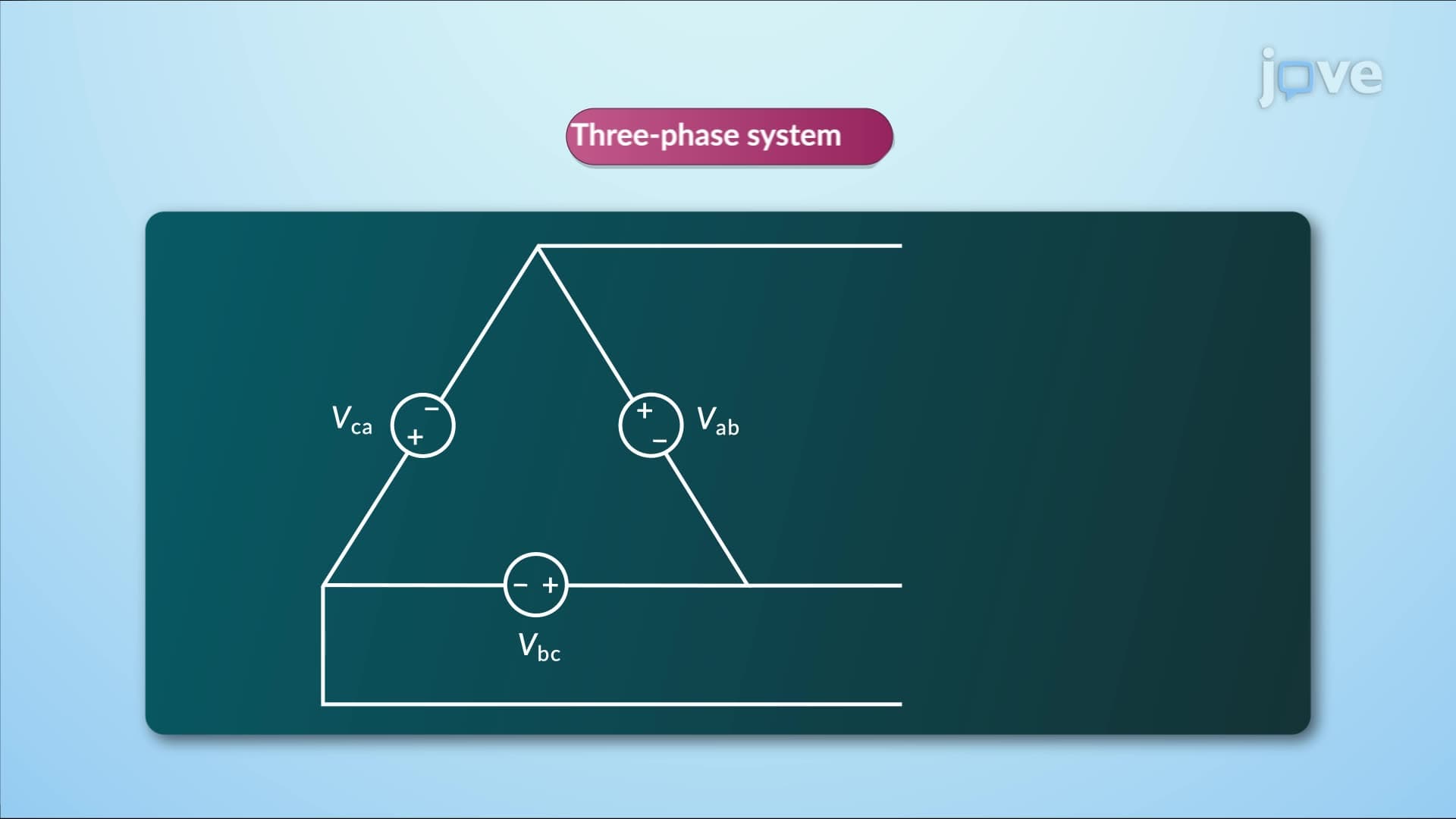
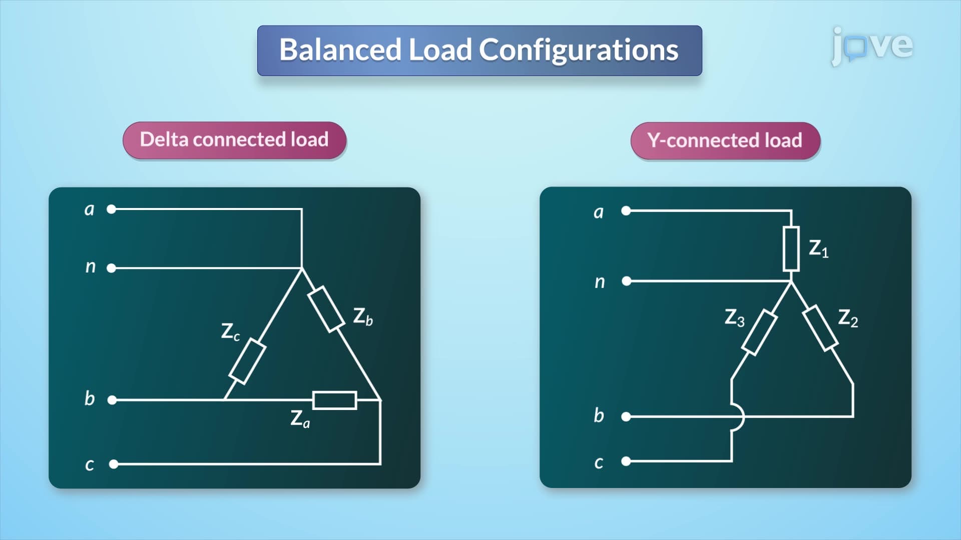
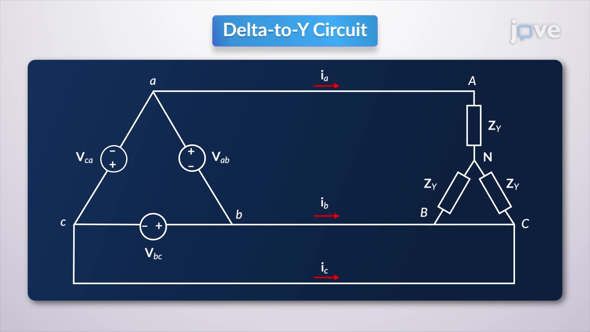
The Y To Y Circuit represents one of the most fundamental configurations in three-phase electrical power systems, forming the standard for electrical distribution across American commercial and industrial facilities. This system consists of two Y-connected components: the source (typically a three-phase generator or transformer) and the load (motors, lighting, or other electrical equipment), connected by a four-wire system that includes three phase conductors and one neutral wire.
The beauty of this configuration lies in its balance. Each phase voltage in a balanced system maintains equal magnitude but differs by exactly 120 degrees in phase angle. This creates a perfectly symmetrical system where, at any given moment, the sum of all three instantaneous voltages equals zero. Major hospitals like Johns Hopkins in Baltimore rely on this principle to ensure uninterrupted power to critical equipment.
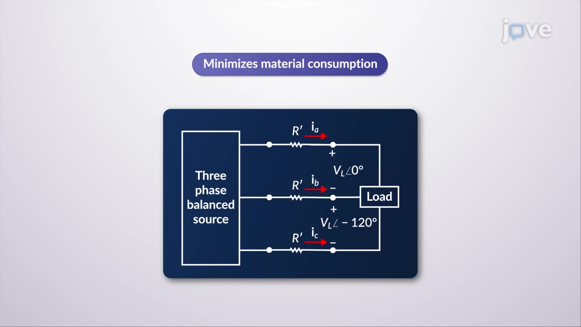
When analyzing The Y To Y Circuit, Kirchhoff's Voltage Law becomes your primary analytical tool. For each phase, the voltage equation accounts for source voltage, line impedance voltage drop, and load voltage. In simplified analysis, we often neglect source and line impedances to focus on core principles-a common approach in introductory electrical engineering courses at institutions like MIT and Stanford.
The line voltages (voltage between any two phases) relate directly to phase voltages through the relationship: V(line) = √3 × V(phase). This √3 factor appears frequently in AP Physics C and college-level electrical engineering exams, making it crucial for academic success.
The most remarkable characteristic of a balanced Y To Y Circuit is the behavior of its currents. Each line current maintains equal magnitude but differs by 120 degrees in phase, mirroring the voltage relationships. When you sum these three currents vectorially, they cancel completely, resulting in zero neutral current. This principle enables efficient power transmission-the neutral wire carries no current in perfect balance.
However, real-world systems rarely achieve perfect balance. Manufacturing facilities like those operated by General Electric experience slight imbalances due to varying loads. When imbalance occurs, the neutral wire begins carrying current equal to the vector sum of the three unbalanced line currents. This concept frequently appears in electrical engineering licensure exams and college circuit analysis courses.
Total power calculation in The Y To Y Circuit follows the simple relationship: P(total) = 3 × P(phase). This three-fold multiplication reflects the additive nature of power in each phase. For single-phase equivalent analysis-a powerful simplification technique-you analyze just one phase and multiply results by three for total system values.
American electrical utilities, including Con Edison serving New York City, use these calculations daily for load planning and system design. Understanding these relationships proves essential for students pursuing electrical engineering degrees and professionals preparing for the Fundamentals of Engineering (FE) exam.
Related Micro-courses