Loading subject page…


16,906 views

Video Summary: What Is Frequency Response of Bjt
Ever wondered why your smartphone amplifier performs differently at bass versus treble frequencies? The cut off frequency of bjt determines exactly when a transistor amplifier stops working effectively at high frequencies. In audio equipment like those manufactured by Texas Instruments, engineers must carefully consider how BJT amplifiers behave across different frequency ranges to ensure optimal sound quality. Understanding the frequency response of BJT reveals why amplifiers have limited bandwidth and how circuit designers overcome these challenges. Watch the full video on JoVE Coach to master this concept with expert-led visuals and step-by-step explanations.
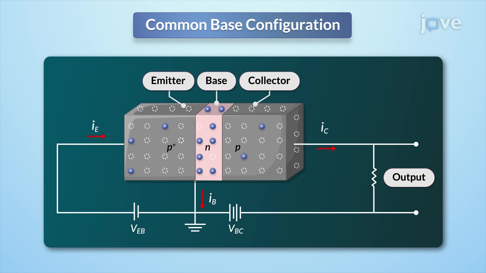
The frequency response of BJT describes how a bipolar junction transistor's amplification characteristics change with signal frequency. Unlike ideal amplifiers that work perfectly at all frequencies, real BJT amplifiers have frequency-dependent behavior that significantly impacts their performance in practical applications.
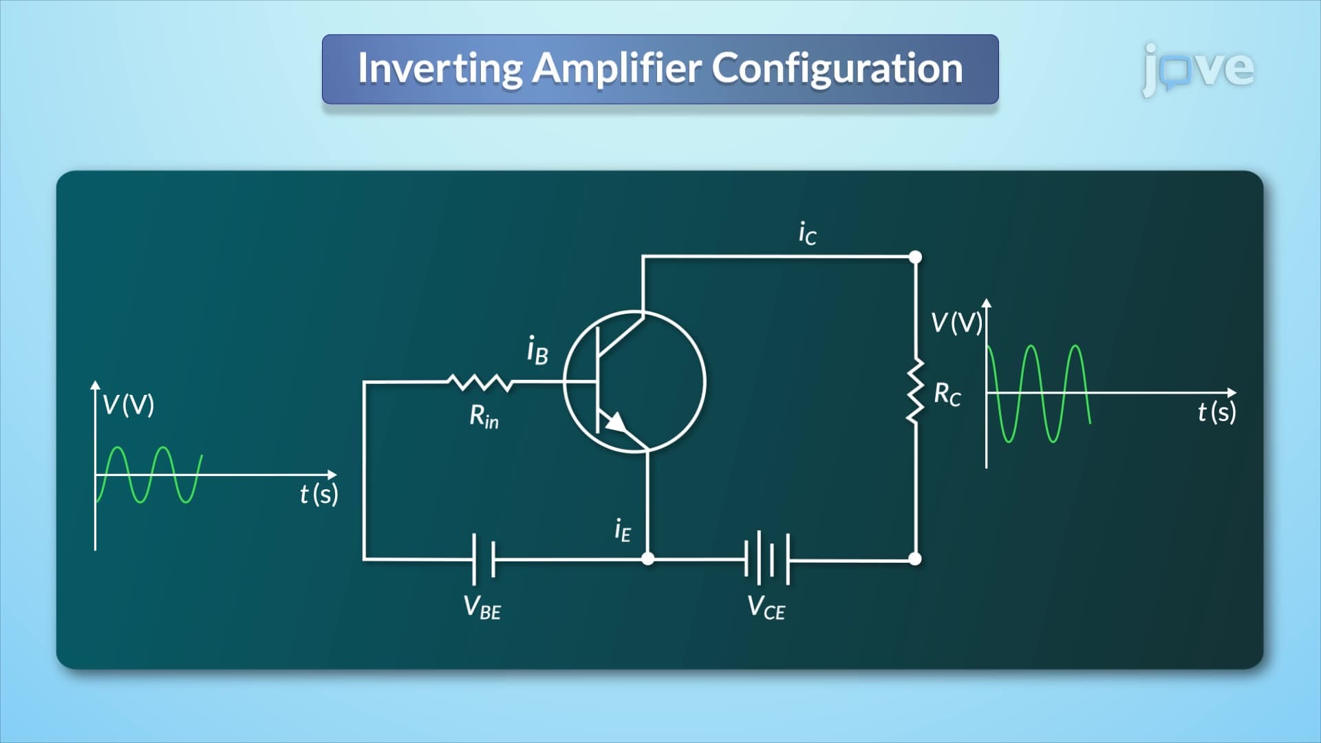
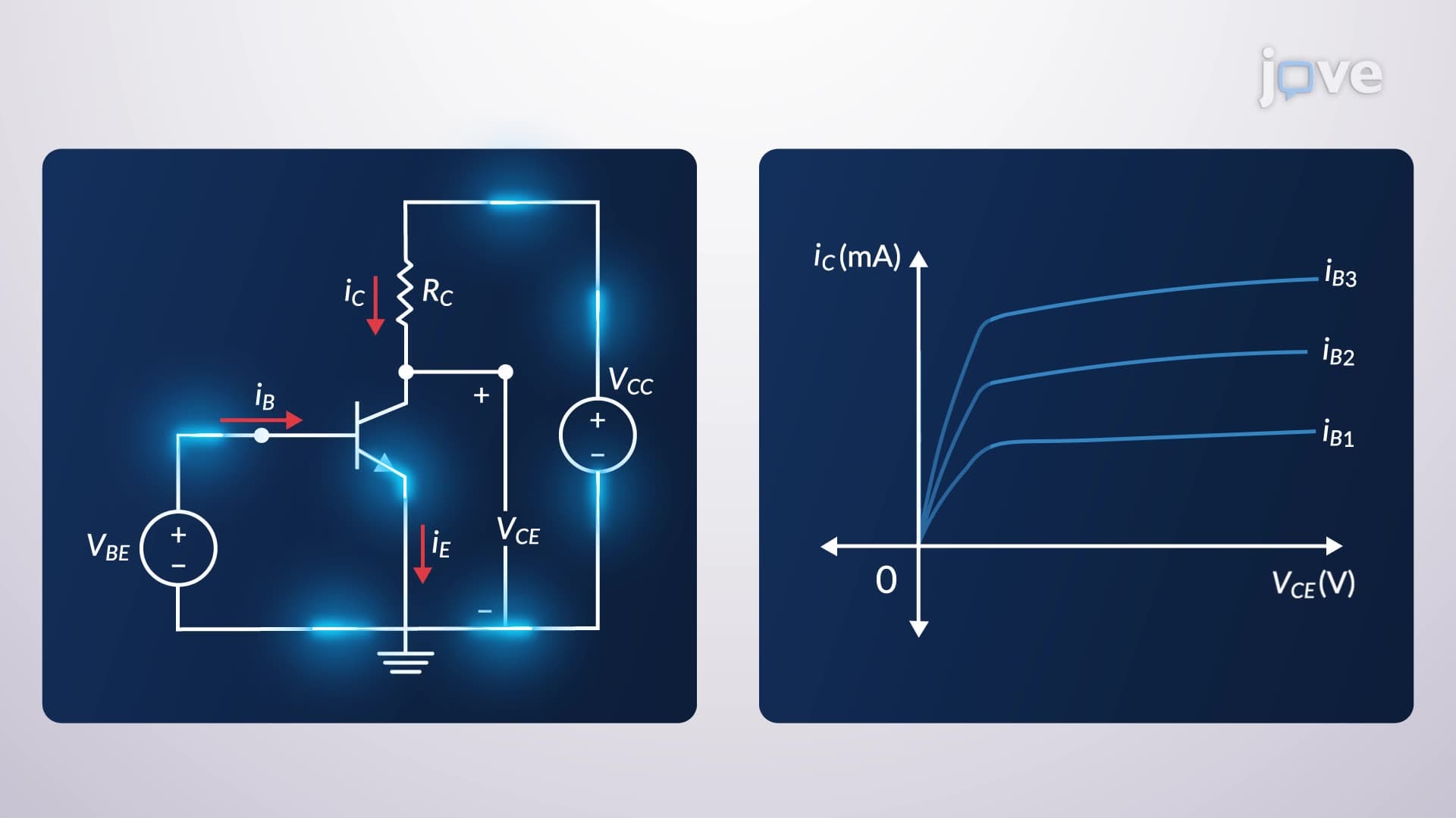
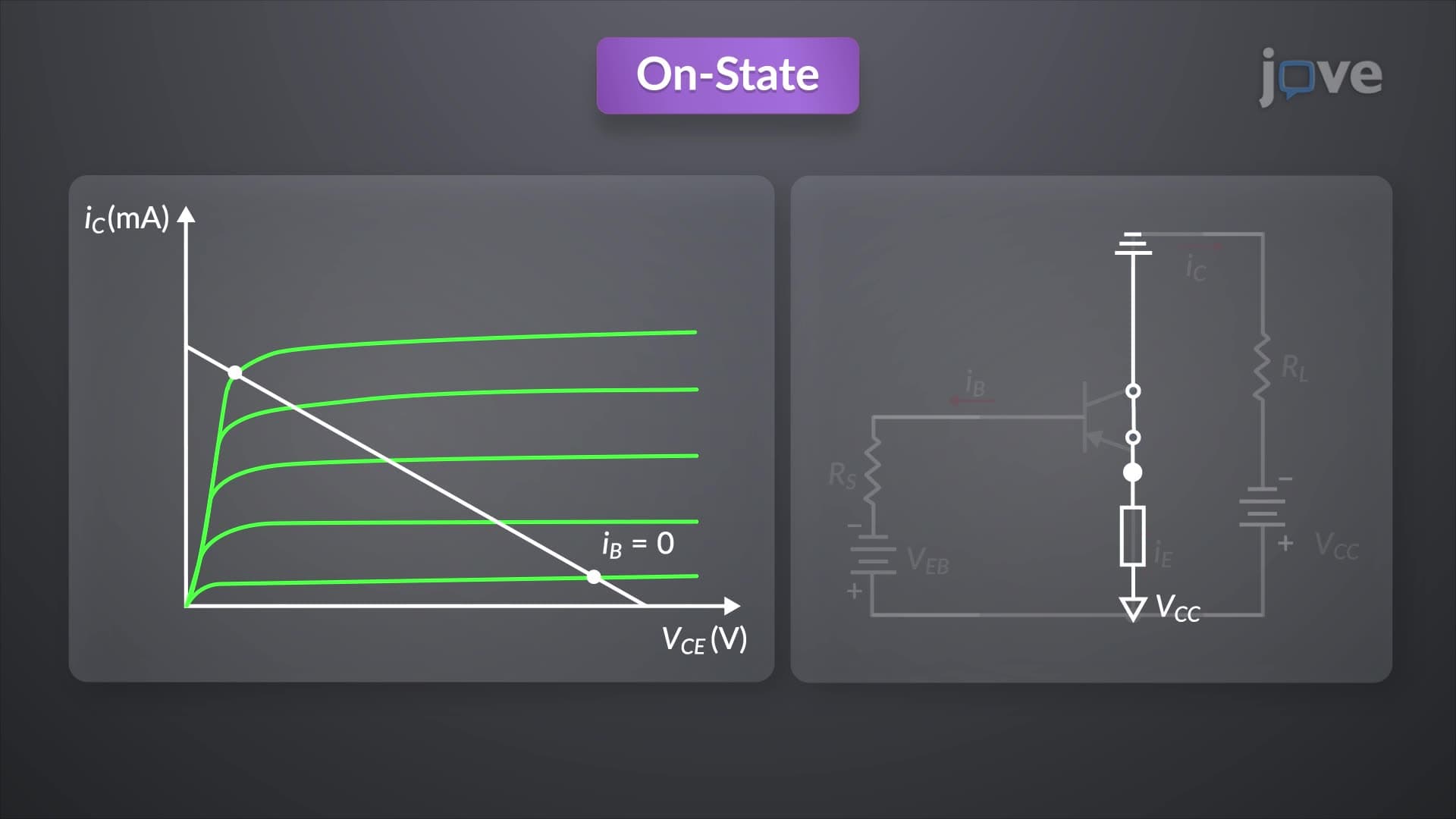
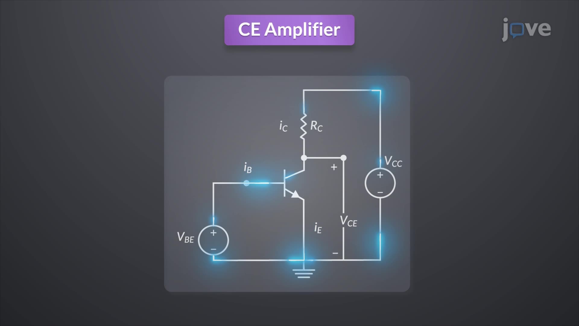
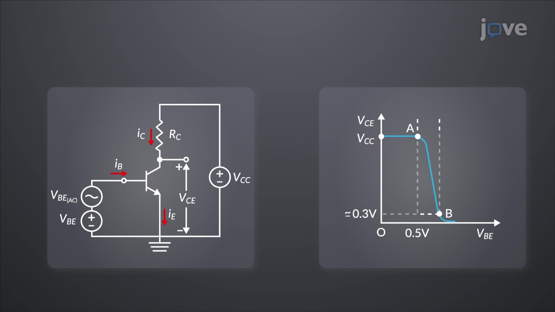
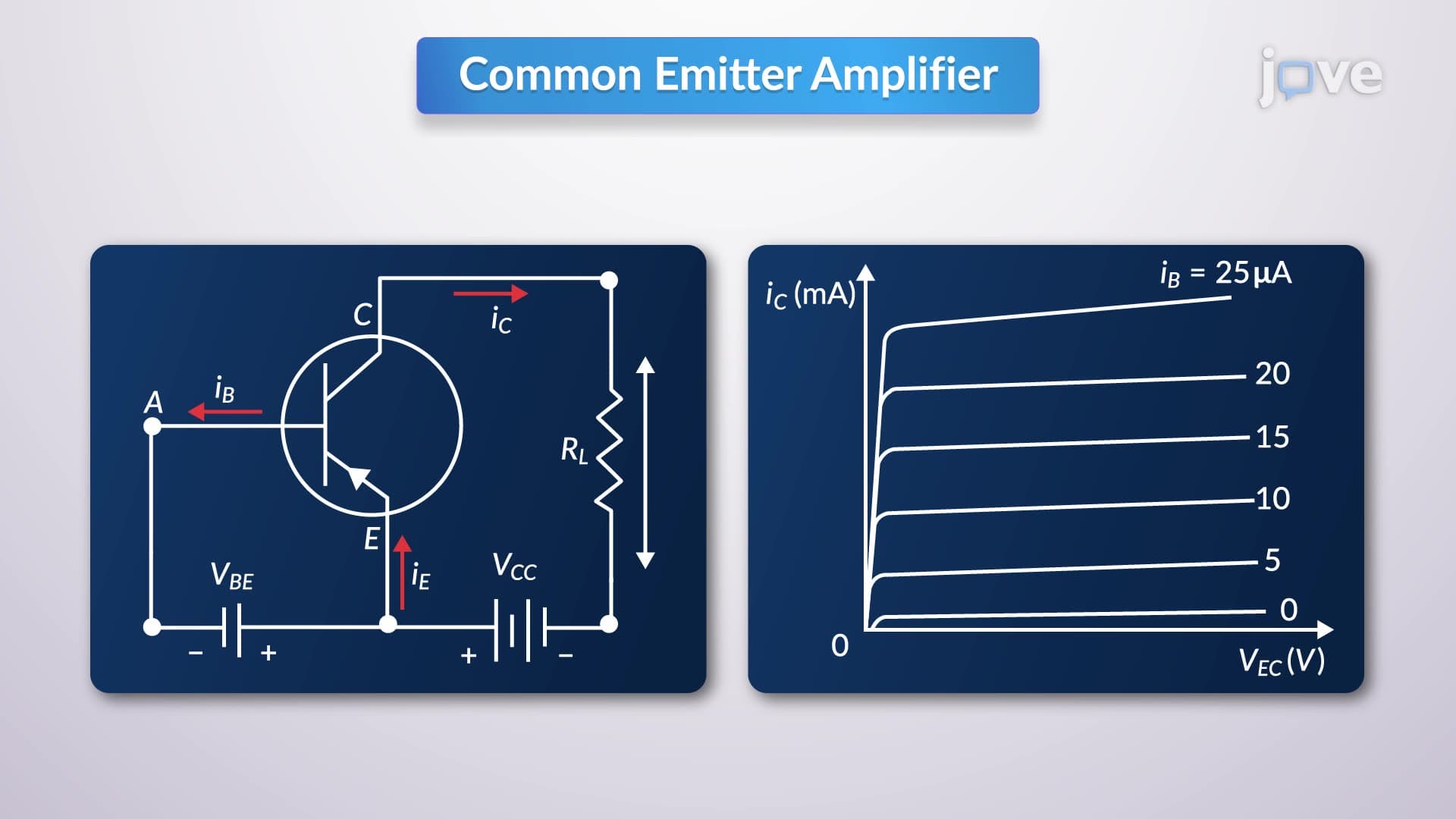
At the heart of BJT operation lies the relationship between DC bias conditions and AC signal amplification. The transistor's operating point, established by base-emitter voltage and collector current, determines the small-signal parameters that govern frequency response. When engineers design amplifiers for companies like Analog Devices or Maxim Integrated, they must carefully balance these parameters to achieve desired performance.
In low-frequency applications, the BJT equivalent circuit primarily consists of resistive elements and transconductance parameters. Transconductance (g_m) represents the crucial relationship between collector current changes and base-emitter voltage variations, typically expressed as g_m = I_C/V_T, where V_T is the thermal voltage (approximately 26 mV at room temperature).
The cut off frequency of bjt becomes critical when understanding amplifier limitations. Input conductance relates base current changes to base-emitter voltage, while output conductance accounts for base width modulation effects. These parameters remain relatively constant at low frequencies, making analysis straightforward for students preparing for AP Physics or college-level electronics courses.
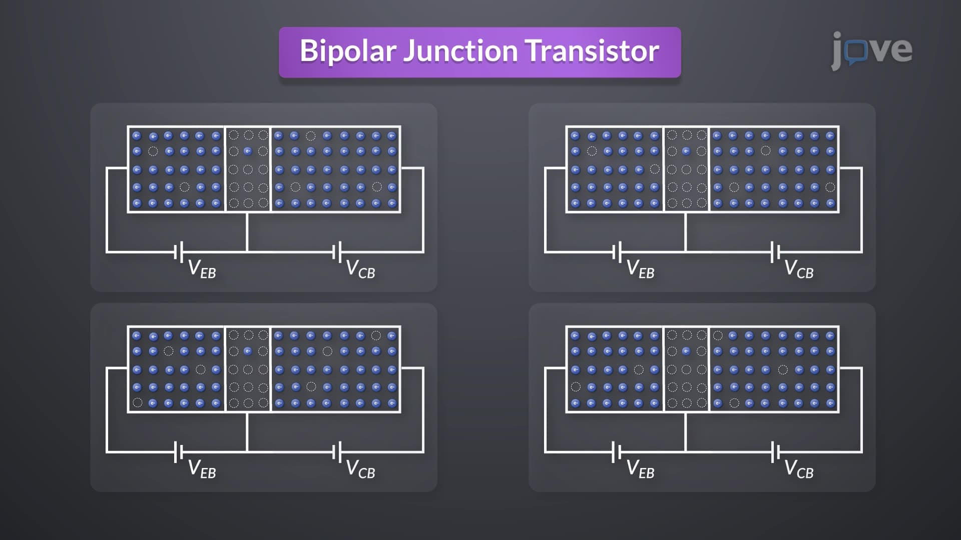
As frequency increases, parasitic capacitances begin dominating BJT behavior. The emitter-base junction exhibits both depletion and diffusion capacitances, while the collector-base junction primarily shows depletion capacitance. These capacitances create frequency-dependent impedances that reduce amplifier gain at higher frequencies.
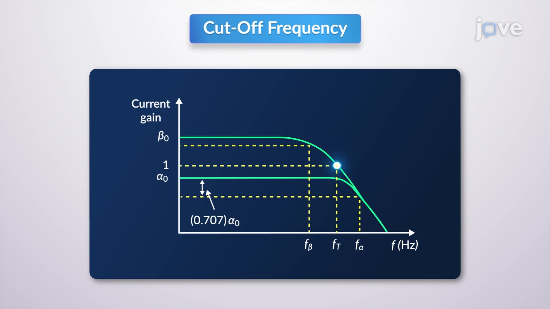
The transition frequency (f_T) represents where current gain drops to unity, marking a fundamental limit of BJT performance. For typical small-signal transistors like the 2N3904, f_T might range from 200-400 MHz, while high-frequency transistors can exceed several GHz. Students studying for the MCAT or engineering entrance exams should understand that this frequency limitation stems from charge storage effects in the transistor junctions.
Modern RF amplifiers in cell phones, WiFi routers, and satellite communications rely heavily on understanding BJT frequency response. Companies like Qualcomm and Broadcom design circuits that operate near transistor frequency limits, requiring sophisticated modeling of high-frequency behavior. The comprehensive high-frequency equivalent circuit includes all resistive and capacitive elements, providing engineers with tools to predict and optimize amplifier performance across the entire frequency spectrum.
Related Micro-courses