Loading subject page…

- Electrical Engineering
- Transistors
- Modes of Operations of BJT
Micro-course: Transistors
16,906 views
Learn key concepts and earn your certificate.

Modes of Operations of BJT

00:00
01:21
Video Summary: Modes of Operations of Bjt Explained
Ever wonder how your smartphone amplifies weak radio signals into clear calls? The frequency response of BJT transistors makes this possible through four distinct operating modes. In circuits powering everything from iPhone amplifiers to Tesla's motor controllers, understanding these modes is crucial for electronics design. The Modes of Operations of BJT Explained reveals how junction biasing determines whether a transistor amplifies, switches, or blocks current flow entirely. Watch the full video on JoVE Coach to master this concept with expert-led visuals and step-by-step explanations.
- Understand the four distinct Modes of Operations of BJT Explained and how junction biasing determines transistor behavior
- Identify the relationship between emitter-base and collector-base junction polarities in each operating mode
- Analyze how active mode enables current amplification with small base currents controlling larger collector currents
- Compare saturation and cut-off modes as electronic switching states in digital circuits
- Evaluate the inverted active mode's reduced current gain due to asymmetric doping concentrations
- Apply BJT operating principles to predict circuit behavior in amplifier and switching applications
- Recognize the role of forward and reverse biasing in controlling electron flow through semiconductor junctions
- Explore practical applications of each mode in modern electronic devices and power systems
Understanding Modes of Operations of BJT Explained
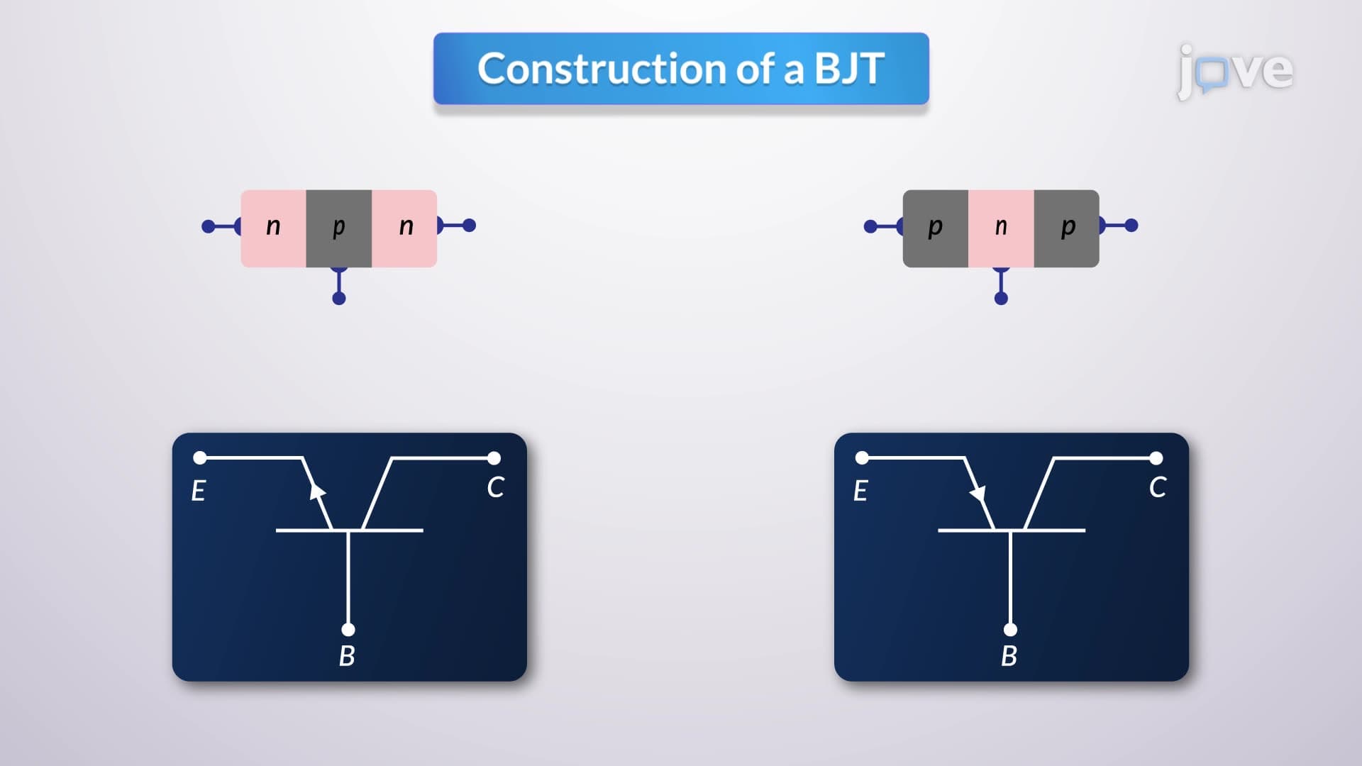
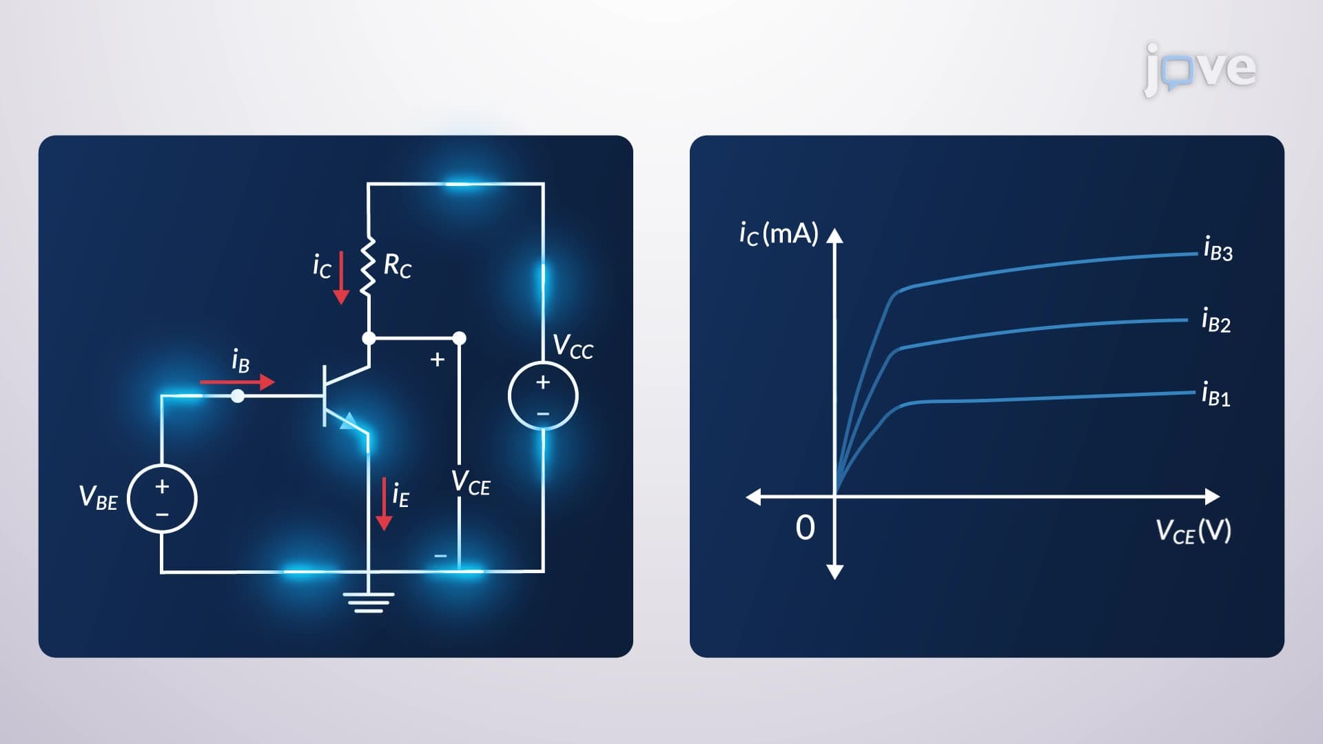
Bipolar junction transistors operate in four fundamental modes determined by the voltage polarities applied across their two PN junctions. The frequency response of BJT circuits depends critically on understanding these operating regions, as each mode exhibits distinct current-voltage characteristics that affect signal processing capabilities.
Active Mode: The Amplification Powerhouse
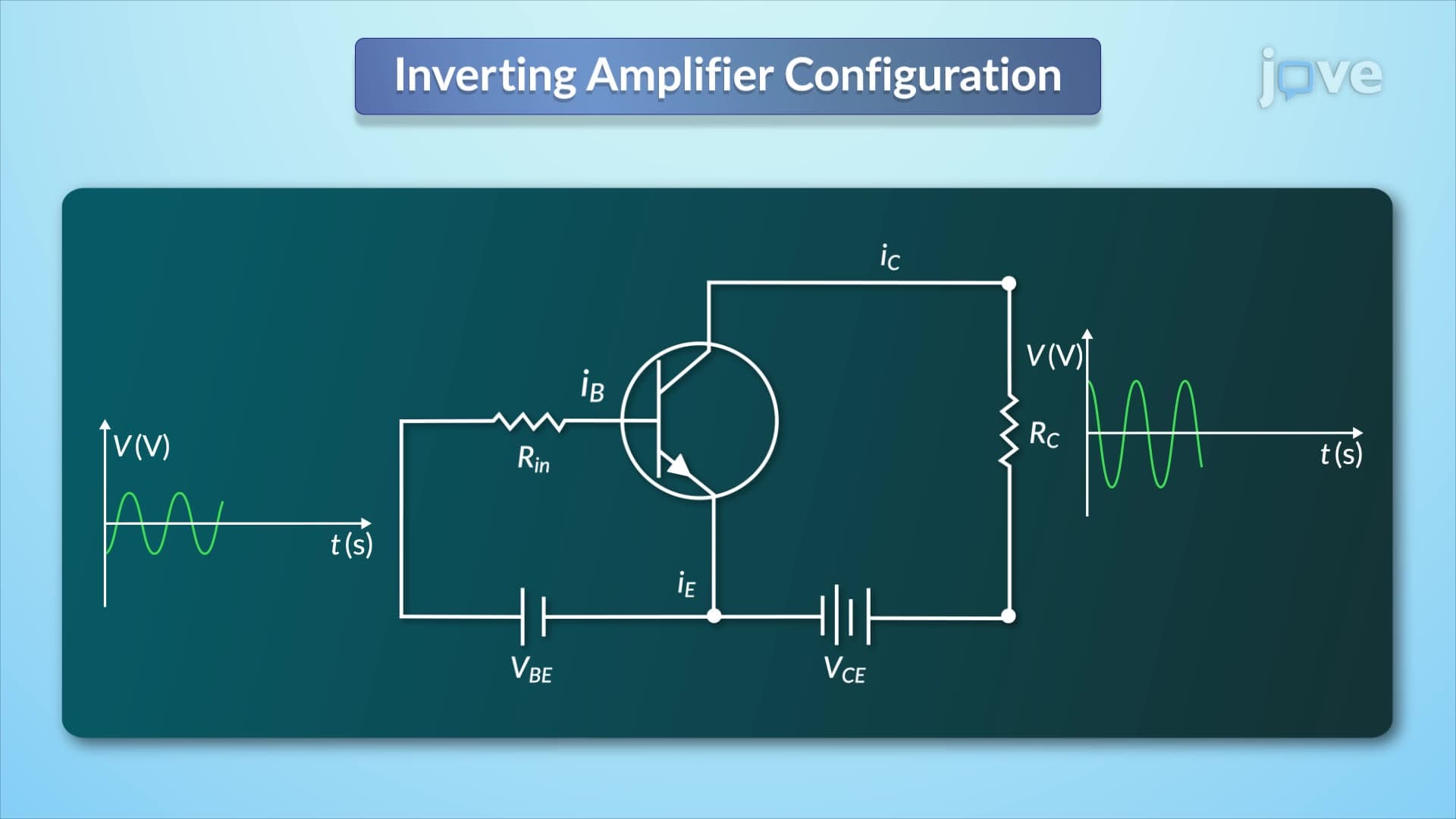
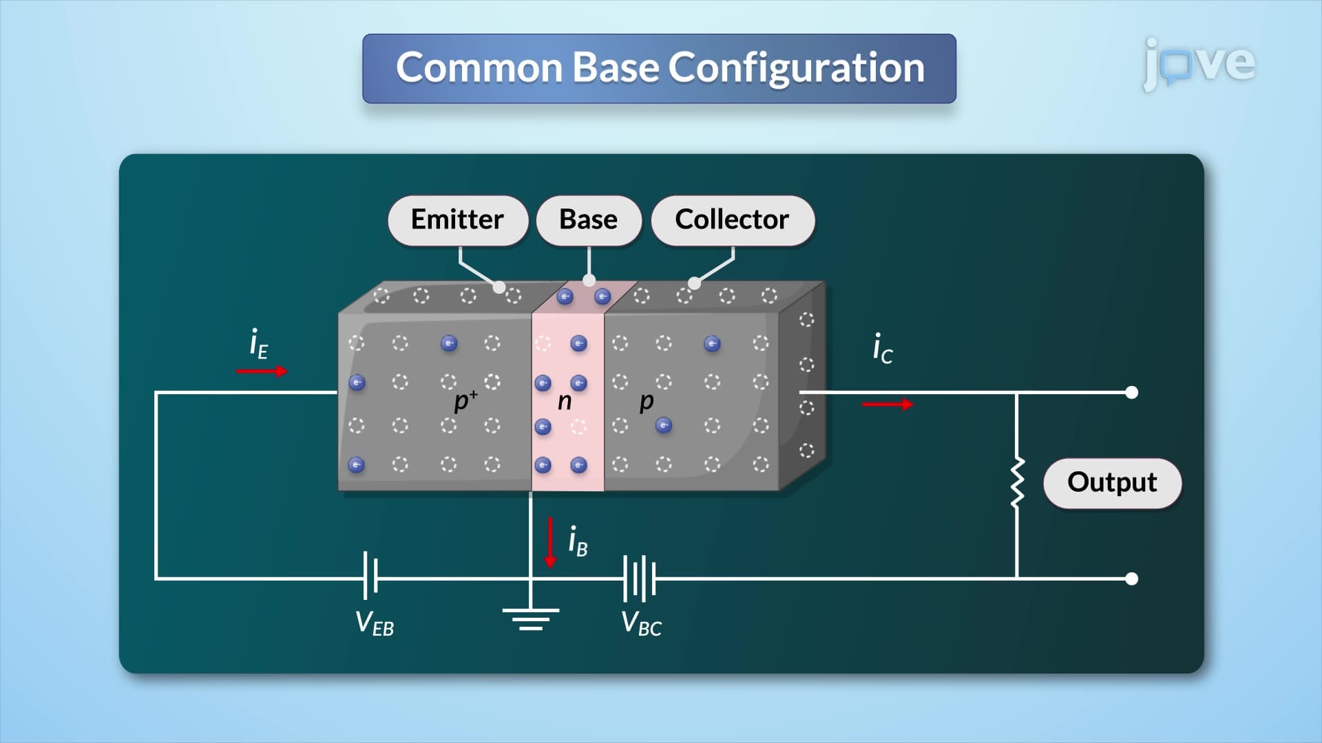
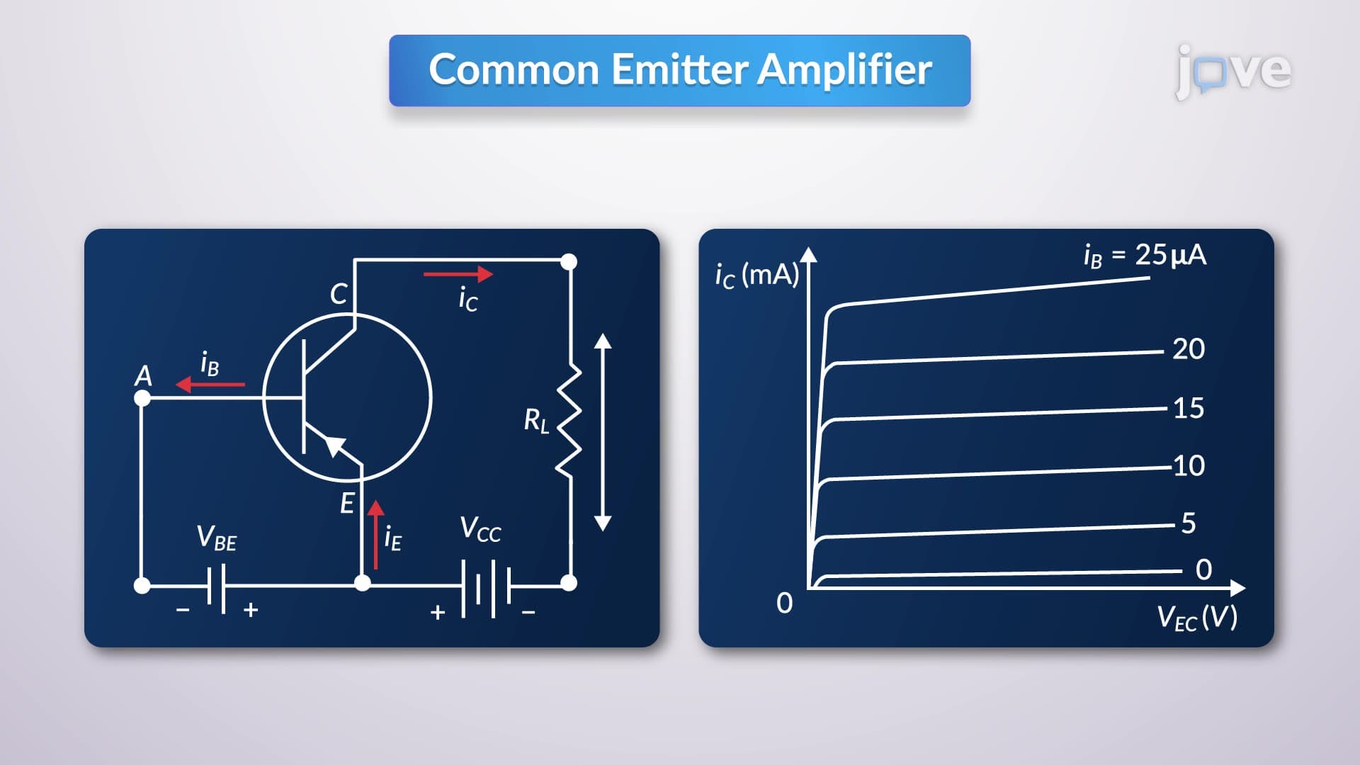
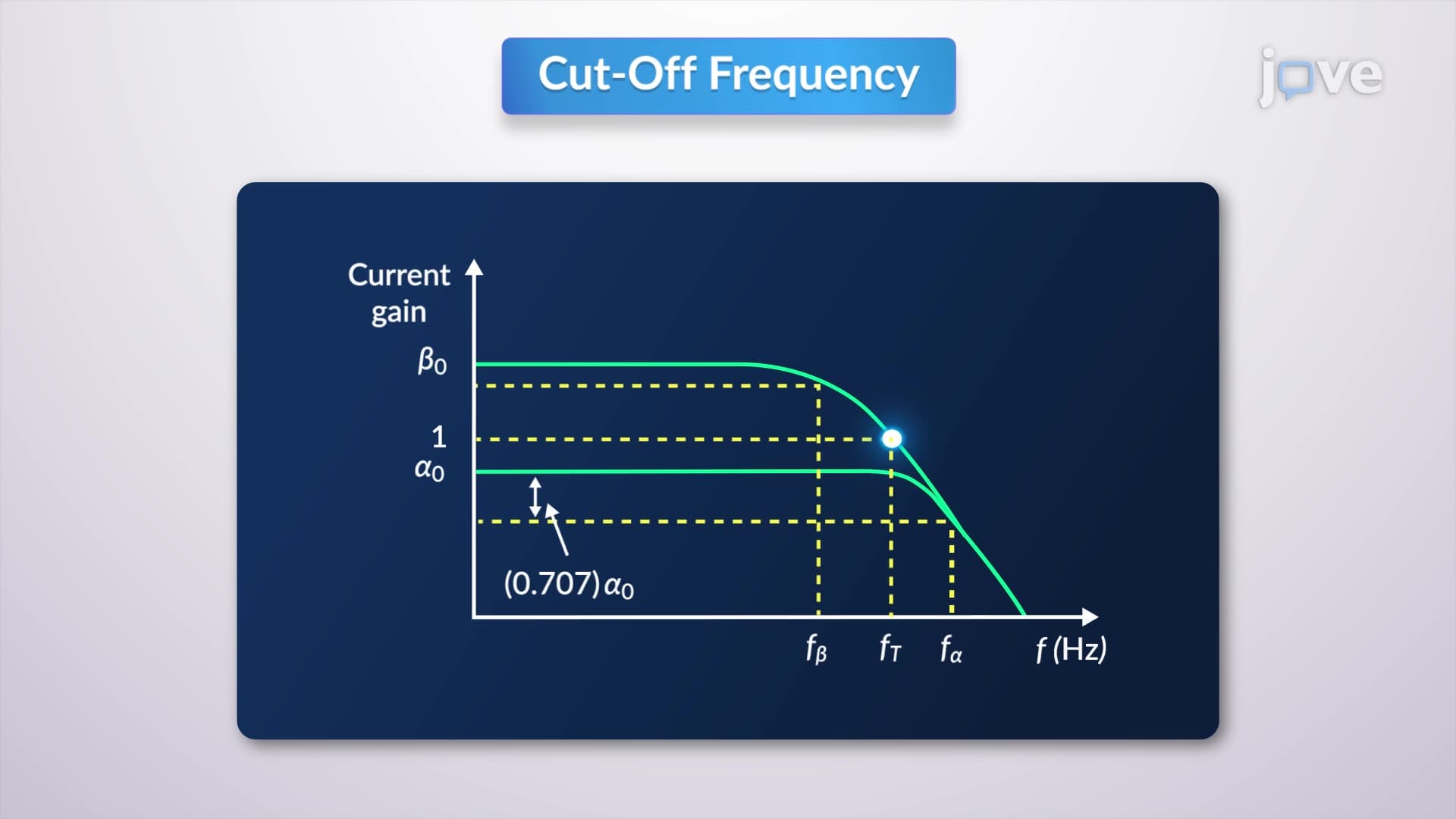
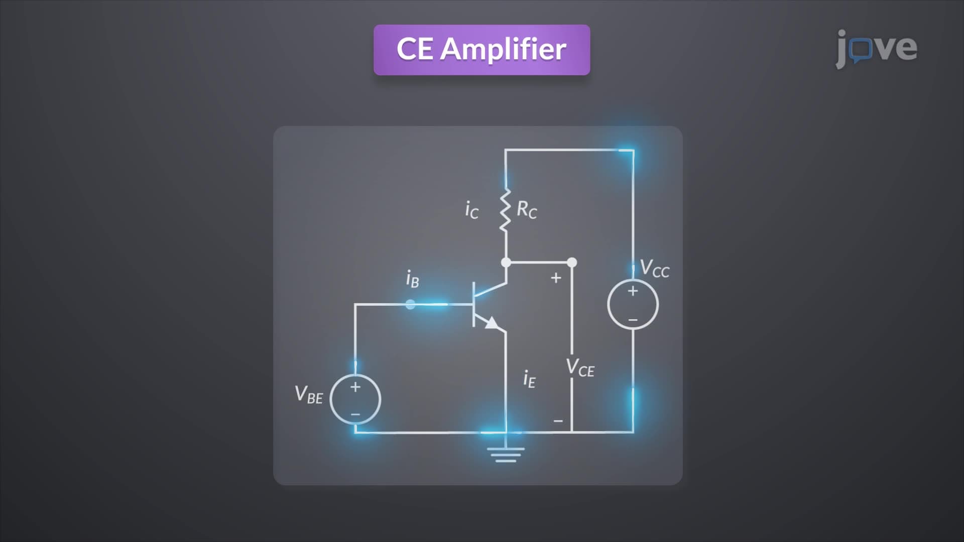
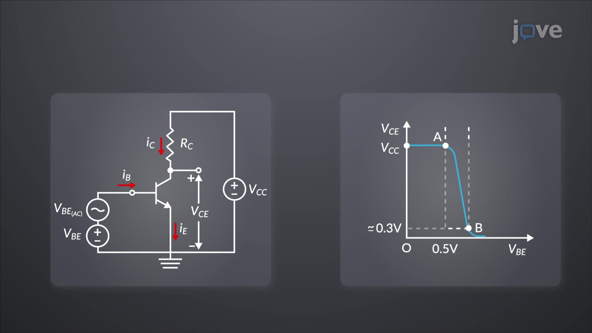
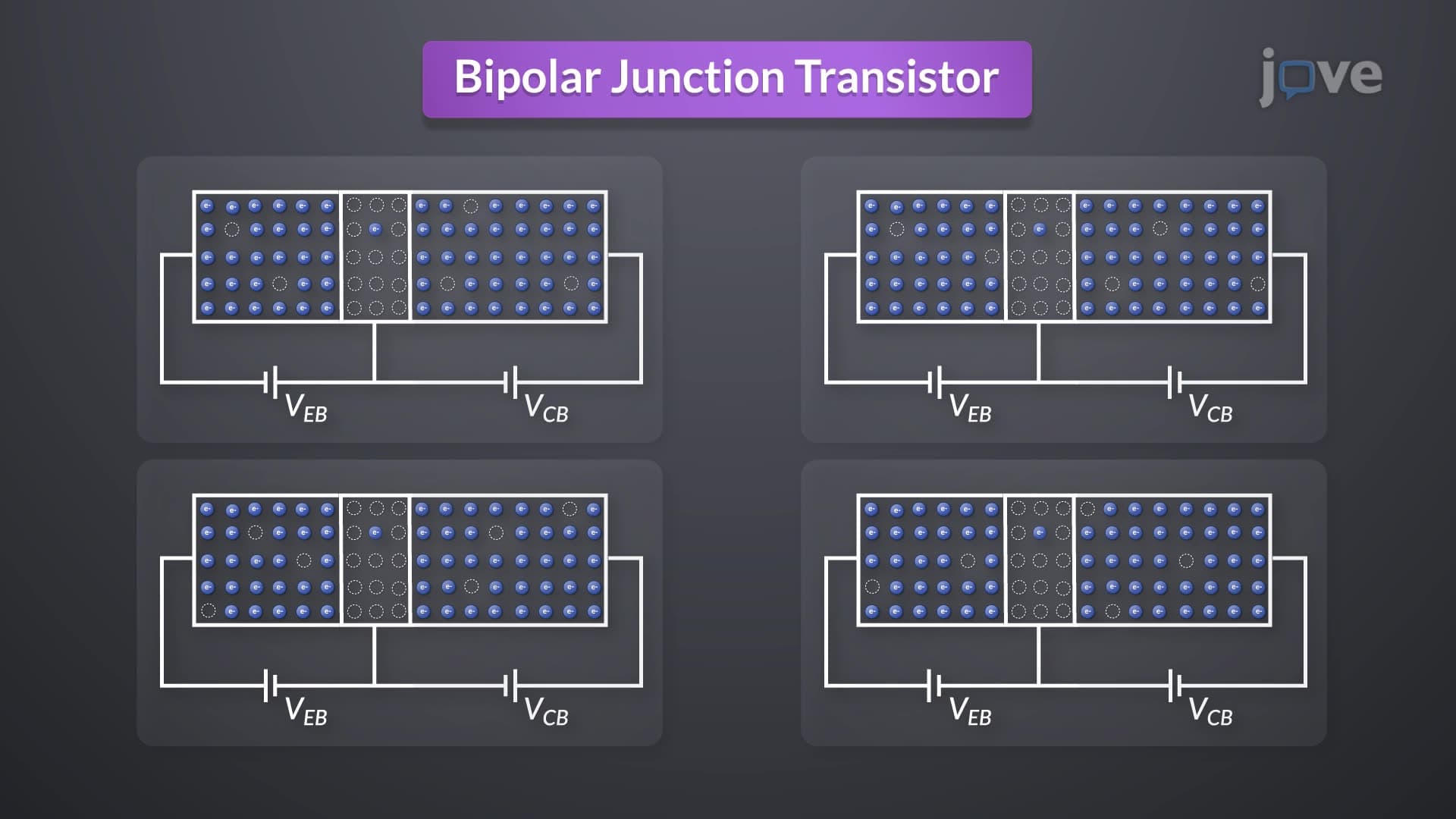
In active mode operation, the emitter-base junction receives forward bias while the collector-base junction operates under reverse bias. This configuration creates optimal conditions for current amplification, where small base current changes produce proportionally larger collector current variations. The frequency response of BJT definition in active mode shows maximum gain at low frequencies, with rolloff occurring at higher frequencies due to junction capacitances.
Modern amplifier circuits in everything from audio equipment to radio frequency systems rely on active mode operation. For instance, the input stages of Fender guitar amplifiers use BJTs in active mode to boost weak pickup signals. Students preparing for AP Physics or college electronics courses should recognize that active mode provides current gain (beta) typically ranging from 50 to 300, making it ideal for signal amplification applications.
Saturation and Cut-off: Digital Switching Modes
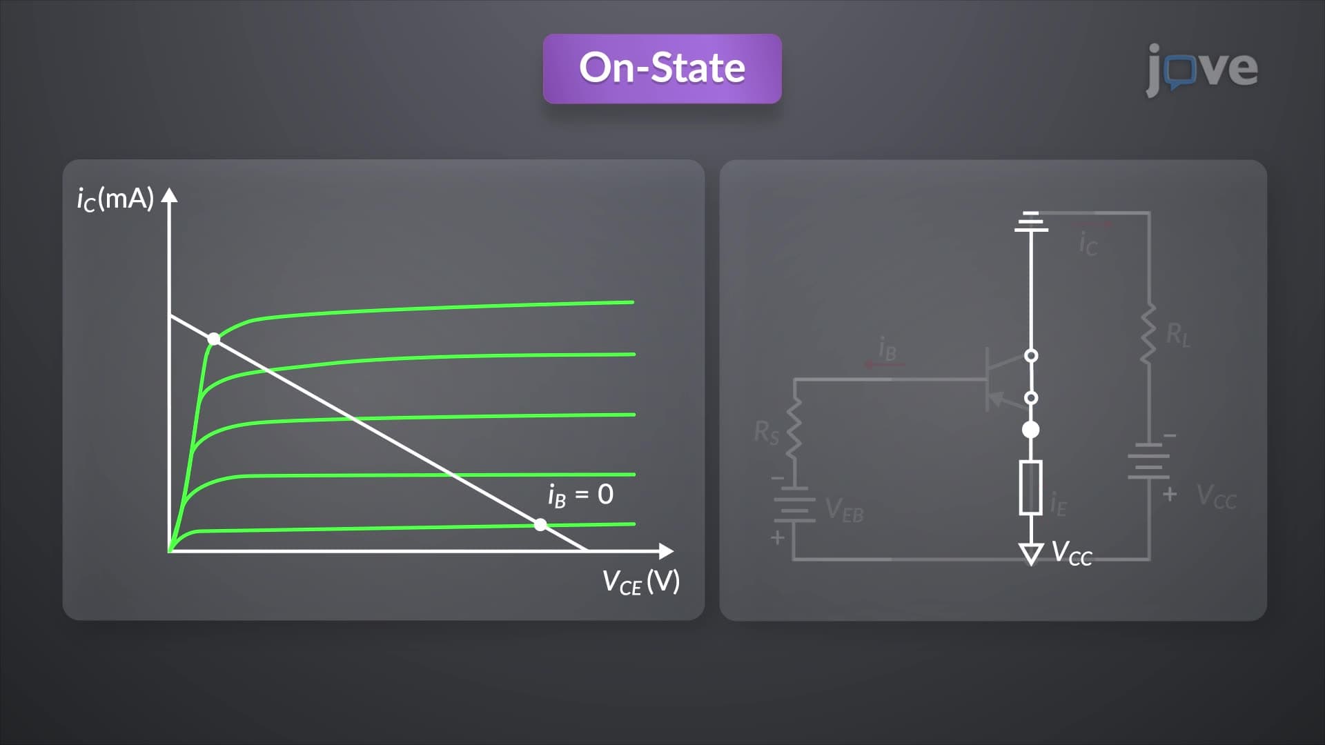
Saturation mode occurs when both junctions are forward-biased, creating a low-resistance path between collector and emitter. This condition mimics a closed switch, with collector-emitter voltage dropping to approximately 0.2V. Conversely, cut-off mode results from reverse-biasing both junctions, creating high resistance that blocks current flow like an open switch.
These switching modes form the foundation of digital electronics. Computer processors, including those in MacBook and Surface devices, utilize billions of BJT-based switches operating between saturation and cut-off states. Understanding frequency response of BJT in switching applications reveals why modern processors achieve gigahertz speeds, the rapid transition between these modes enables high-frequency digital operations.
Inverted Active Mode: The Reverse Configuration
Inverted mode reverses normal operation by forward-biasing the collector-base junction while reverse-biasing the emitter-base junction. Although functionally similar to active mode, the frequency response of BJT concept in inverted operation shows reduced current gain due to asymmetric doping profiles optimized for standard operation.
This mode rarely appears in practical circuits but understanding its characteristics proves valuable for comprehensive BJT analysis, particularly in advanced college coursework and engineering applications where transistor modeling requires complete characterization across all operating regions.
Frequently Asked Questions
BJT operates in four modes: active (amplification), saturation (closed switch), cut-off (open switch), and inverted active (reverse amplification). Each mode determines whether the transistor amplifies signals, conducts current freely, blocks current flow, or provides reduced gain amplification. Understanding these modes is essential for designing amplifier and switching circuits.
Frequency response describes how BJT gain varies with signal frequency in each operating mode. Active mode shows highest gain at low frequencies with rolloff at higher frequencies due to parasitic capacitances. Switching modes (saturation/cut-off) enable high-frequency digital operations through rapid state transitions.
Active and switching modes (saturation/cut-off) dominate exam questions because they represent practical applications. Expect problems involving amplifier gain calculations in active mode and digital logic circuits using saturation/cut-off switching. MCAT may include basic transistor switching concepts in physics sections.
Active mode powers audio amplifiers, radio frequency circuits, and sensor interfaces requiring signal amplification. Saturation and cut-off modes create digital switches in processors, memory circuits, and power management systems. Modern devices integrate millions of BJTs operating across these modes simultaneously.
Inverted mode reverses junction biasing, using the collector as emitter and vice versa. This produces lower current gain because transistor doping profiles are optimized for standard operation. While rarely used practically, understanding inverted mode demonstrates complete BJT characterization principles.
Basic algebra and understanding of voltage/current relationships suffice for fundamental concepts. Focus on junction biasing principles and current flow directions rather than complex equations. High school physics and introductory college electronics courses provide adequate mathematical background.
Create comparison charts showing junction biasing, current flow, and applications for each mode. Practice identifying modes from given bias conditions and predicting circuit behavior. Use online circuit simulators to visualize mode transitions and reinforce theoretical understanding with hands-on experience.
Progress to frequency response analysis, small-signal modeling, and amplifier configurations (common-emitter, common-base, common-collector). Advanced studies include thermal effects, noise analysis, and integrated circuit design principles used in modern semiconductor devices.
Related Micro-courses

11 Concepts

7 Concepts

5 Concepts