Loading subject page…

- Electrical Engineering
- Transistors
- Configurations of BJT
Micro-course: Transistors
16,906 views
Learn key concepts and earn your certificate.
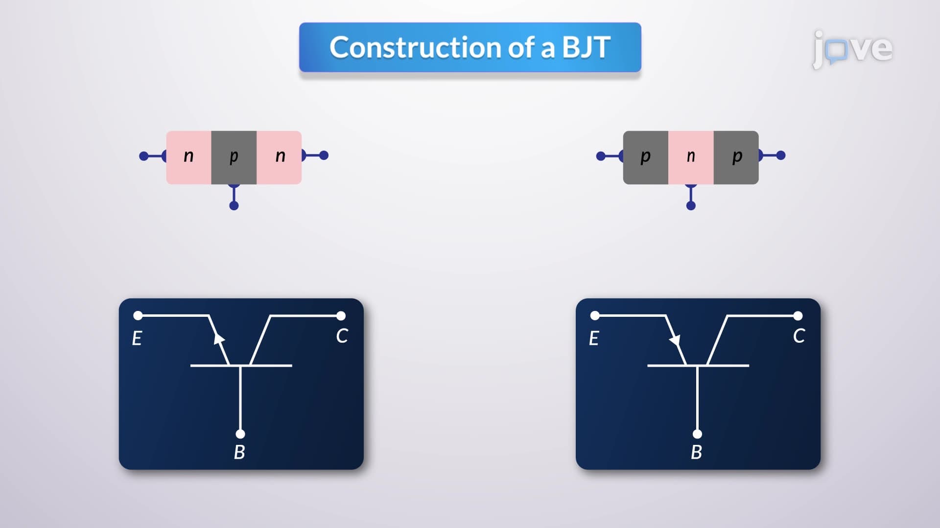


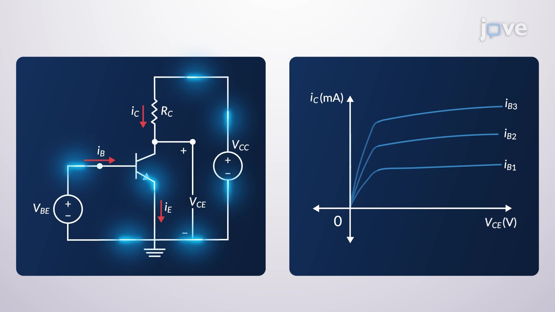

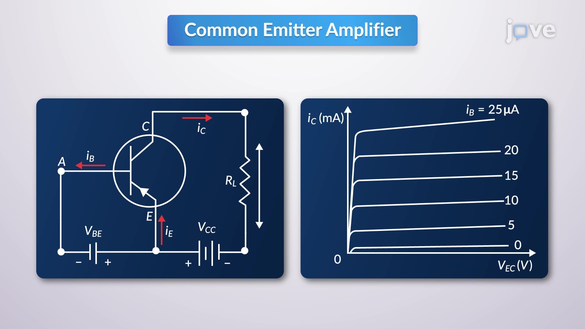

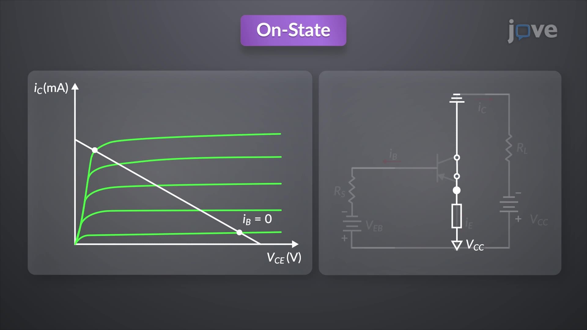









Configurations of BJT


00:00
01:16
Video Summary: What Is Configurations of Bjt
Ever wondered how your smartphone amplifier boosts audio signals with such precision? The working principle of BJT configurations determines how bipolar junction transistors function in different circuit arrangements. Understanding configurations of BJT is crucial for grasping how devices like hearing aids manufactured by companies such as Phonak USA achieve their remarkable signal processing capabilities. These three fundamental configurations-common base, common emitter, and common collector-each offer unique advantages for specific electronic applications. Watch the full video on JoVE Coach to master this concept with expert-led visuals and step-by-step explanations.
- Understand the three primary configurations of BJT and their distinguishing characteristics in circuit design
- Identify the common terminal that defines each BJT configuration and its impact on signal processing
- Analyze the voltage gain, current gain, and impedance properties of common base, common emitter, and common collector configurations
- Compare the phase relationships between input and output signals across different BJT arrangements
- Evaluate the practical applications where each configuration excels, from microphone pre-amplifiers to impedance matching circuits
- Apply knowledge of BJT configurations to solve circuit analysis problems in electronics coursework
- Recognize how input and output impedance characteristics determine the suitability of each configuration for specific applications
- Explore the relationship between transistor terminal arrangements and their resulting amplification properties
Understanding Configurations of BJT Fundamentals
The working principle of BJT configurations centers on which terminal serves as the common connection between input and output circuits. This seemingly simple concept profoundly impacts how the transistor behaves electrically. Each of the three configurations-common base (CB), common emitter (CE), and common collector (CC)-exhibits distinct characteristics that make them suitable for different applications in modern electronics.
The working principle of BJT definition encompasses how the shared terminal influences current flow, voltage amplification, and signal phase relationships. Students preparing for AP Physics or college-level electronics courses must grasp that the common terminal doesn't simply serve as a passive connection point-it actively determines the transistor's operational characteristics.
Common Base Configuration: High Voltage, Low Current
The common base configuration connects the base terminal to both input and output circuits, typically through a ground connection. This arrangement produces exceptional voltage gain, often exceeding 100, making it ideal for applications requiring significant voltage amplification with minimal current draw. Companies like Shure Incorporated utilize this configuration in high-end microphone pre-amplifiers for professional recording studios.
However, the working principle of BJT in detail reveals a crucial limitation: current attenuation. The collector current is always less than the emitter current due to base recombination losses, resulting in a current gain less than unity. This characteristic makes the common base configuration unsuitable for applications requiring current amplification.
Common Emitter Configuration: The Versatile Amplifier
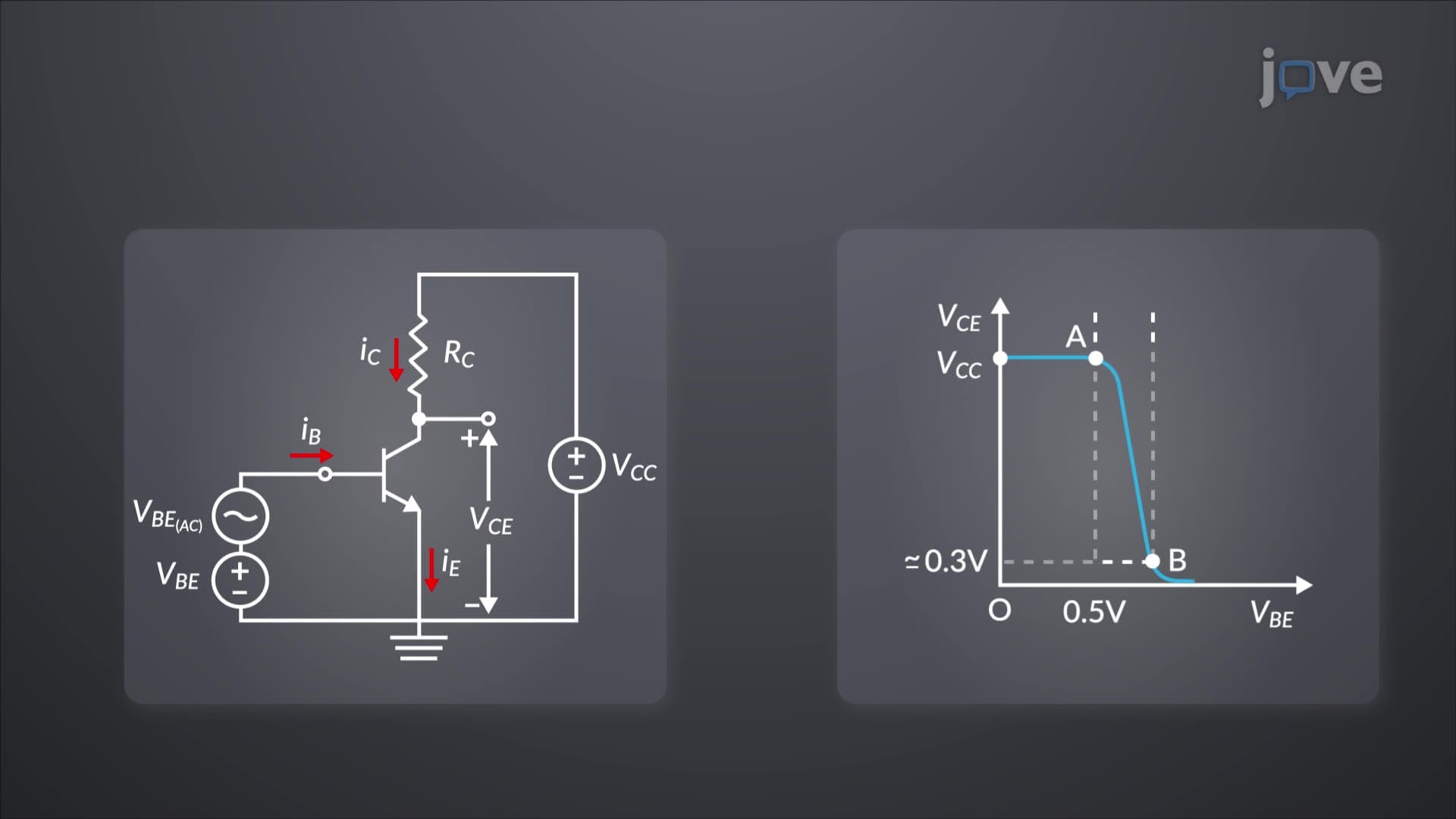
The common emitter configuration represents the most widely used BJT arrangement in amplifier circuits. With the emitter terminal serving as the common connection, this configuration delivers substantial current gain, voltage gain, and power gain simultaneously. Texas Instruments frequently incorporates this configuration in their operational amplifier designs for consumer electronics.
A critical aspect of the working principle of basics involves understanding the 180-degree phase inversion between input and output signals. This inverting characteristic proves advantageous in many applications, including audio amplifiers and signal processing circuits commonly tested in MCAT physics sections.
Common Collector Configuration: The Impedance Matcher
The common collector configuration, also known as an emitter follower or voltage follower, prioritizes impedance matching over voltage gain. With voltage gain less than unity, this configuration might seem counterintuitive, but its high input impedance and low output impedance make it invaluable for buffering applications.
Medical device manufacturers like Medtronic leverage this configuration in implantable devices where signal integrity across different circuit stages is paramount. The working principle of BJT concept demonstrates how this configuration maintains signal voltage while providing substantial current amplification and excellent impedance characteristics.
Frequently Asked Questions
Configurations of BJT refer to three circuit arrangements where different transistor terminals serve as common connections between input and output. They're crucial because each configuration offers unique amplification properties, impedance characteristics, and phase relationships that determine their suitability for specific electronic applications from audio amplifiers to medical devices.
AP Physics C often tests BJT configuration concepts through circuit analysis problems focusing on current flow, voltage relationships, and power calculations. Students typically encounter questions comparing voltage gains, identifying configuration types from circuit diagrams, and calculating impedance values for different arrangements.
College exams frequently test configuration identification from circuit diagrams, calculation of voltage and current gains, analysis of frequency response characteristics, and selection of appropriate configurations for given design requirements. MCAT physics sections may include BJT concepts in circuit analysis contexts.
Companies like Boston Scientific use common collector configurations in pacemaker circuits for impedance matching, while hearing aid manufacturers employ common emitter configurations for audio signal amplification. These applications demonstrate how different configurations serve specific biomedical engineering requirements in FDA-approved devices.
Basic algebra and understanding of Ohm's law suffice for fundamental BJT configuration concepts. While advanced analysis involves calculus-based AC circuit theory, high school students can grasp core principles through DC analysis and basic voltage/current relationships taught in introductory physics courses.
Focus on creating comparison charts highlighting each configuration's key characteristics, practice identifying configurations from circuit diagrams, and work through numerical problems calculating gains and impedances. Use memory aids like "Common Emitter = Current gain" to remember distinctive properties during timed exams.
Understanding BJT configurations provides foundation knowledge for operational amplifier internal circuitry studied in advanced electronics courses. Many op-amp designs incorporate multiple BJT configurations within single integrated circuits, making this knowledge essential for students pursuing electrical engineering or biomedical engineering degrees.
Advanced studies include frequency response analysis, thermal stability considerations, and MOSFET configurations that parallel BJT principles. Students often progress to studying differential amplifiers, current mirrors, and integrated circuit design where BJT configuration concepts form fundamental building blocks.
Related Micro-courses

11 Concepts

7 Concepts

5 Concepts