Loading…
Loading video…

25,808 views
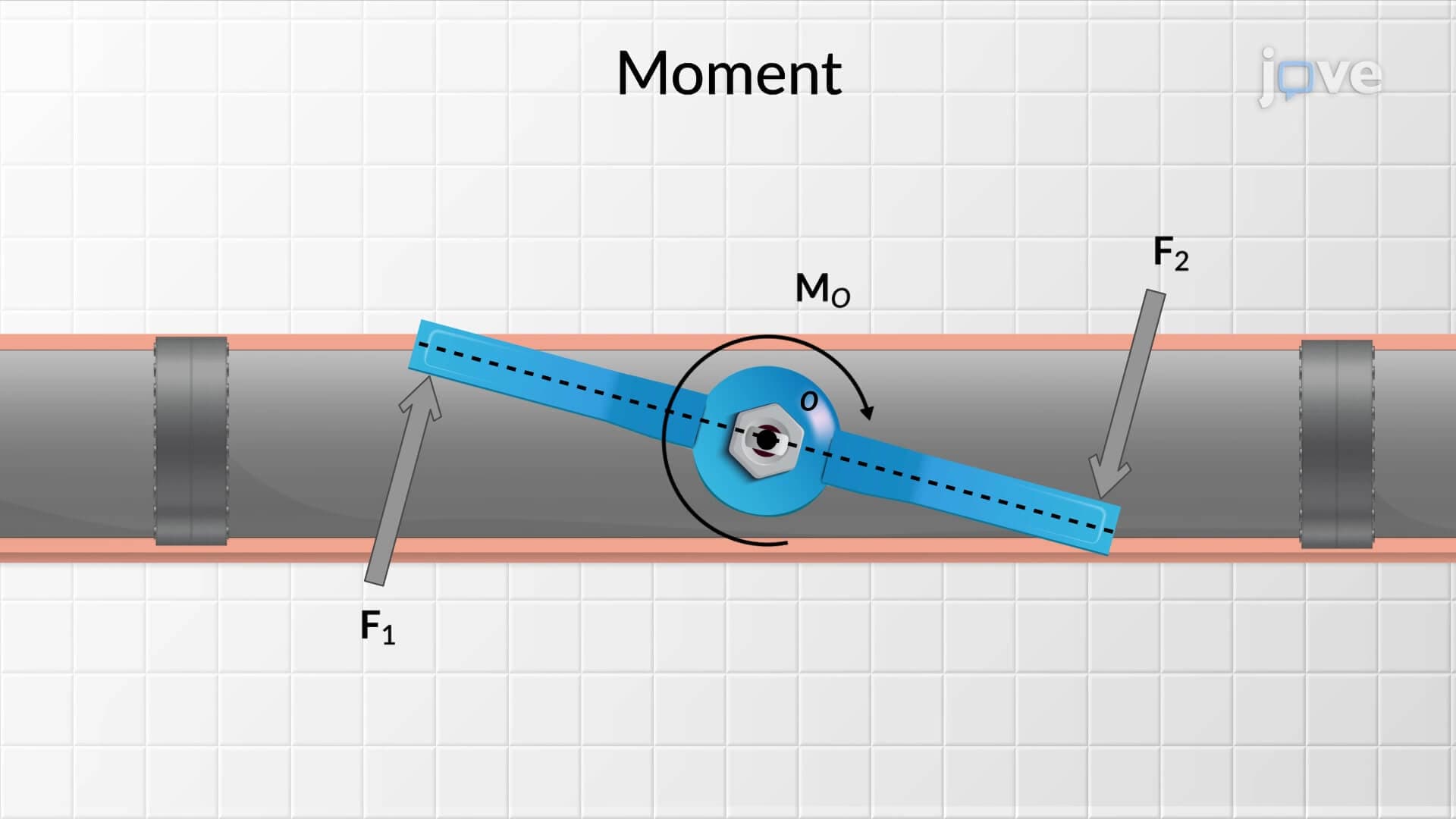
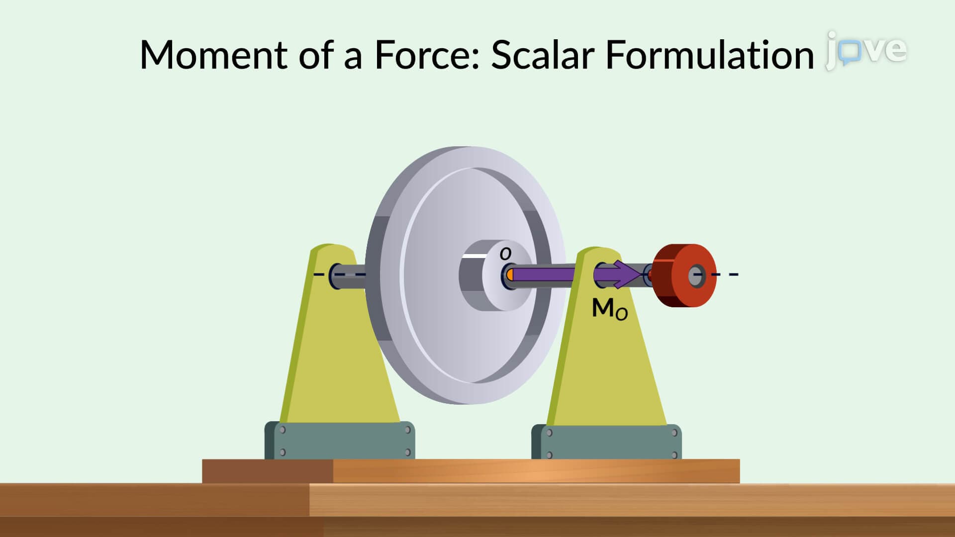
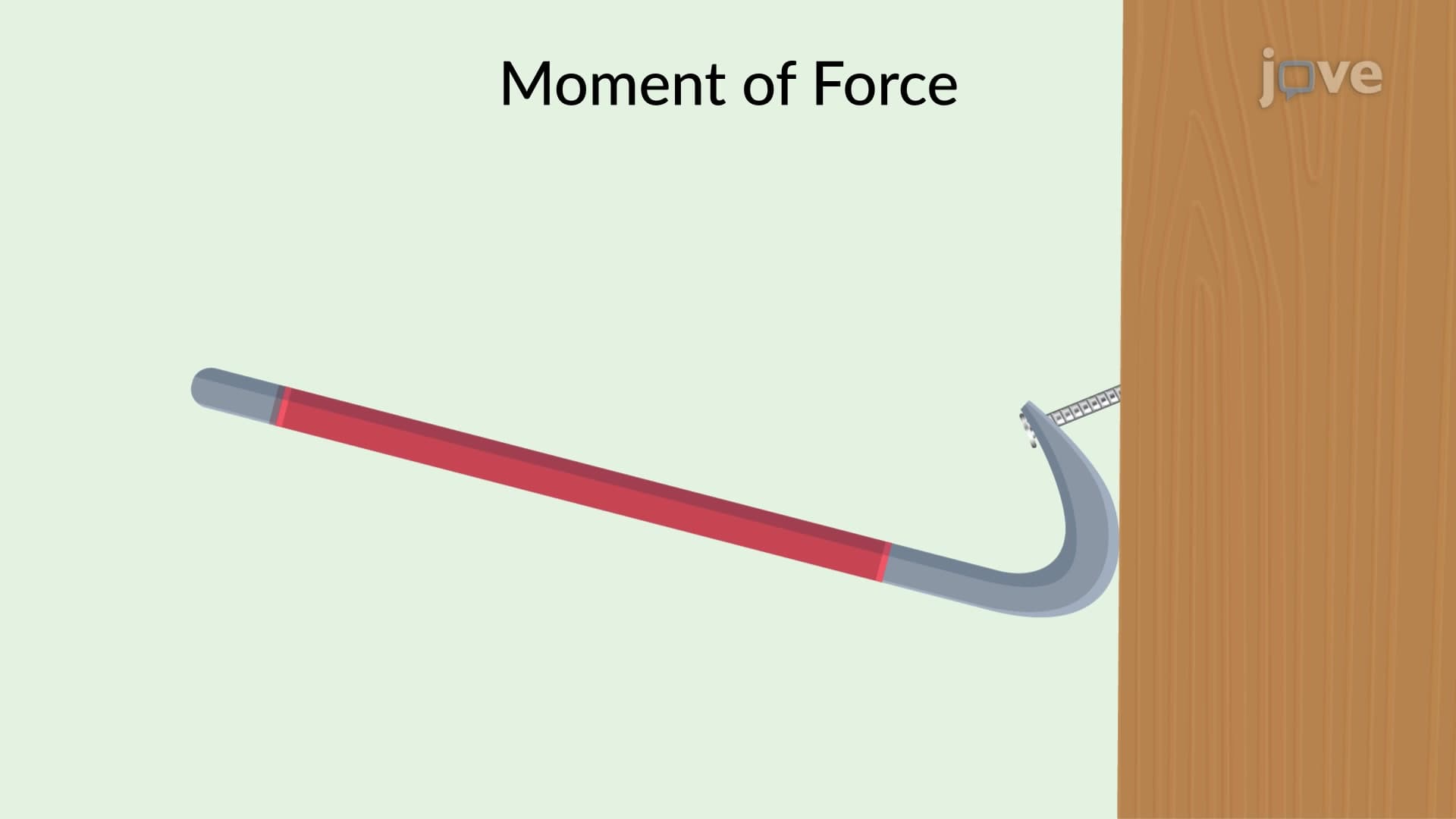
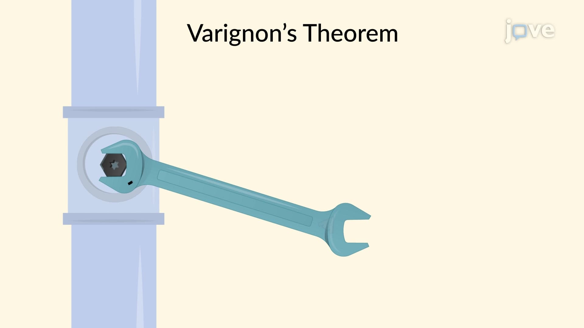
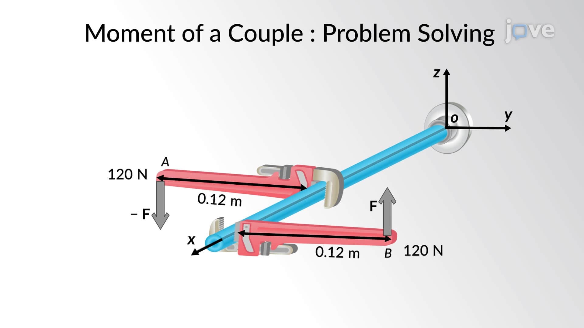
Ever wonder why a wrench works better with a longer handle, or how engineers calculate the twisting forces on a wind turbine tower during storms? Resultant moment vector formulation provides the mathematical framework to analyze these rotational effects when multiple forces act on objects. Consider construction cranes lifting heavy steel beams—engineers must calculate how various forces create moments that could cause dangerous rotation. What is Resultant Moment Vector Formulation becomes essential for determining the combined rotational effect of all applied forces using vector mathematics and cross-product operations. Watch the full video on JoVE Coach to master this concept with expert-led visuals and step-by-step explanations.
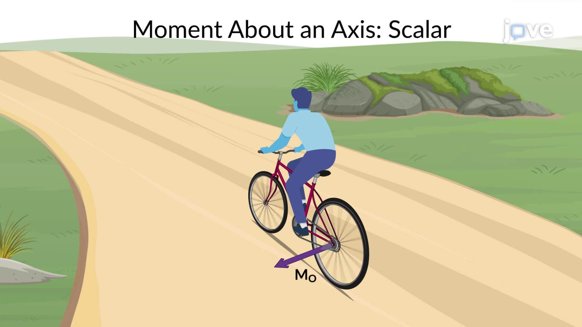
Resultant moment vector formulation represents a sophisticated mathematical approach to analyzing the combined rotational effects of multiple forces acting on rigid bodies. Unlike simple scalar moments that only consider magnitude, vector formulation captures both the magnitude and directional characteristics of rotational tendencies in three-dimensional space. This concept proves essential for engineering students preparing for advanced coursework and professionals designing everything from bridge structures to aircraft components.
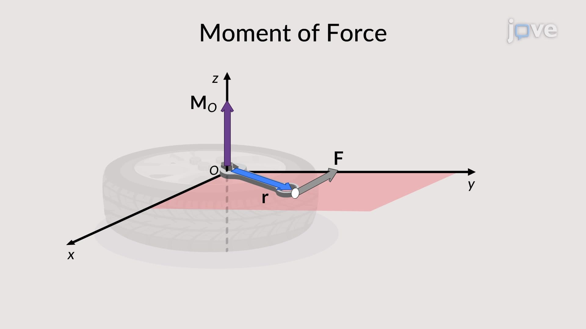
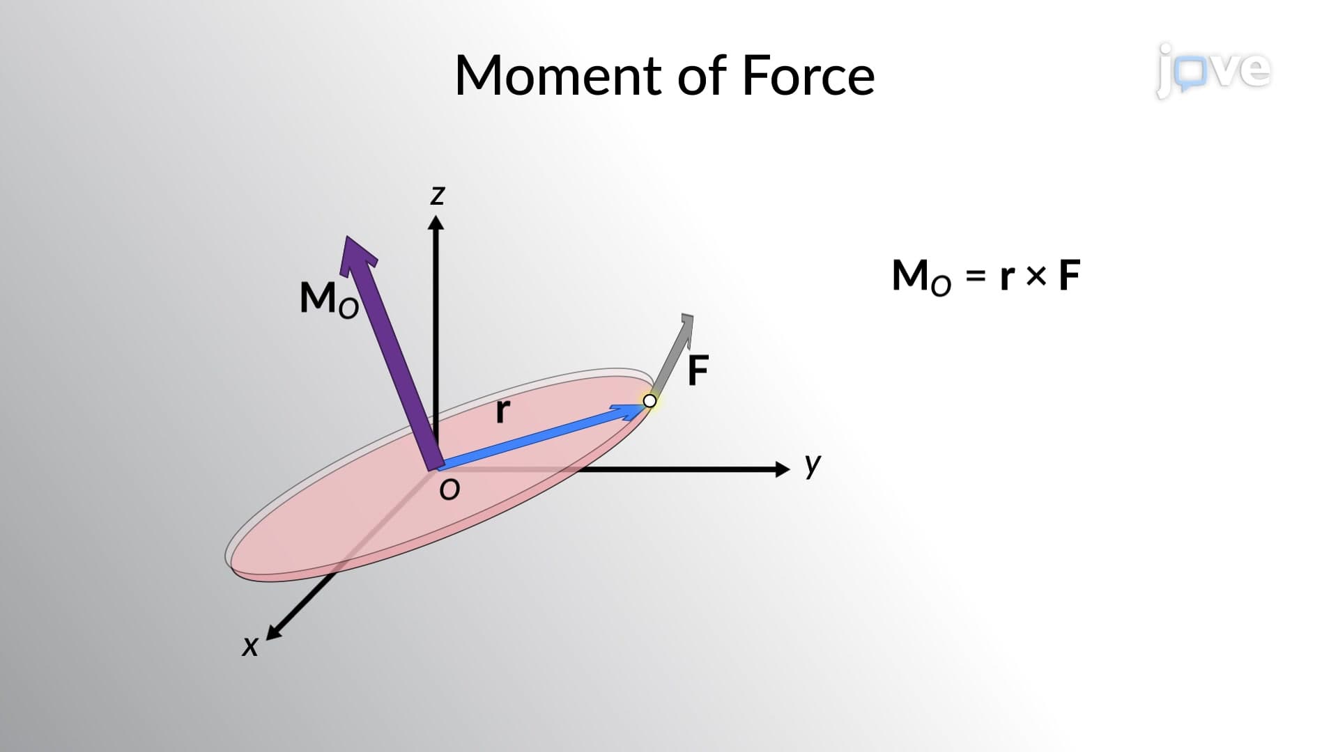
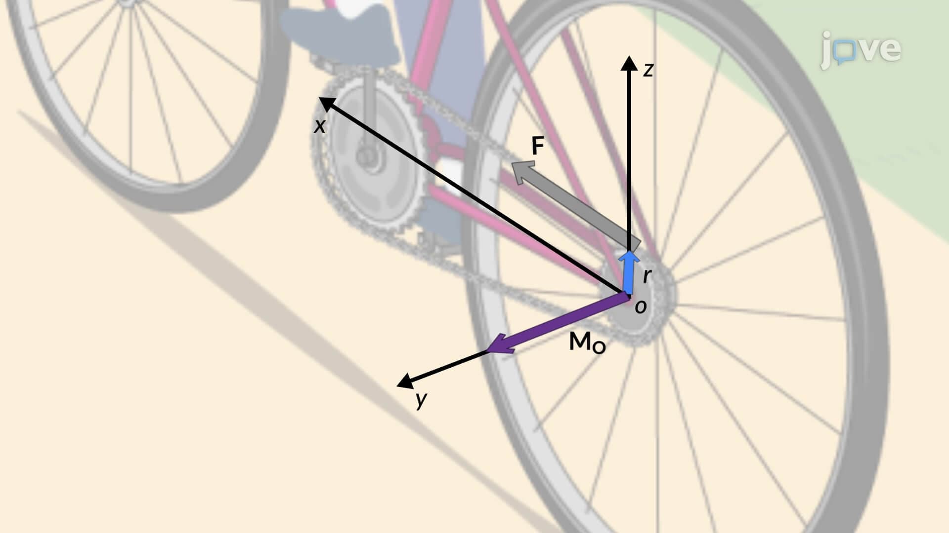
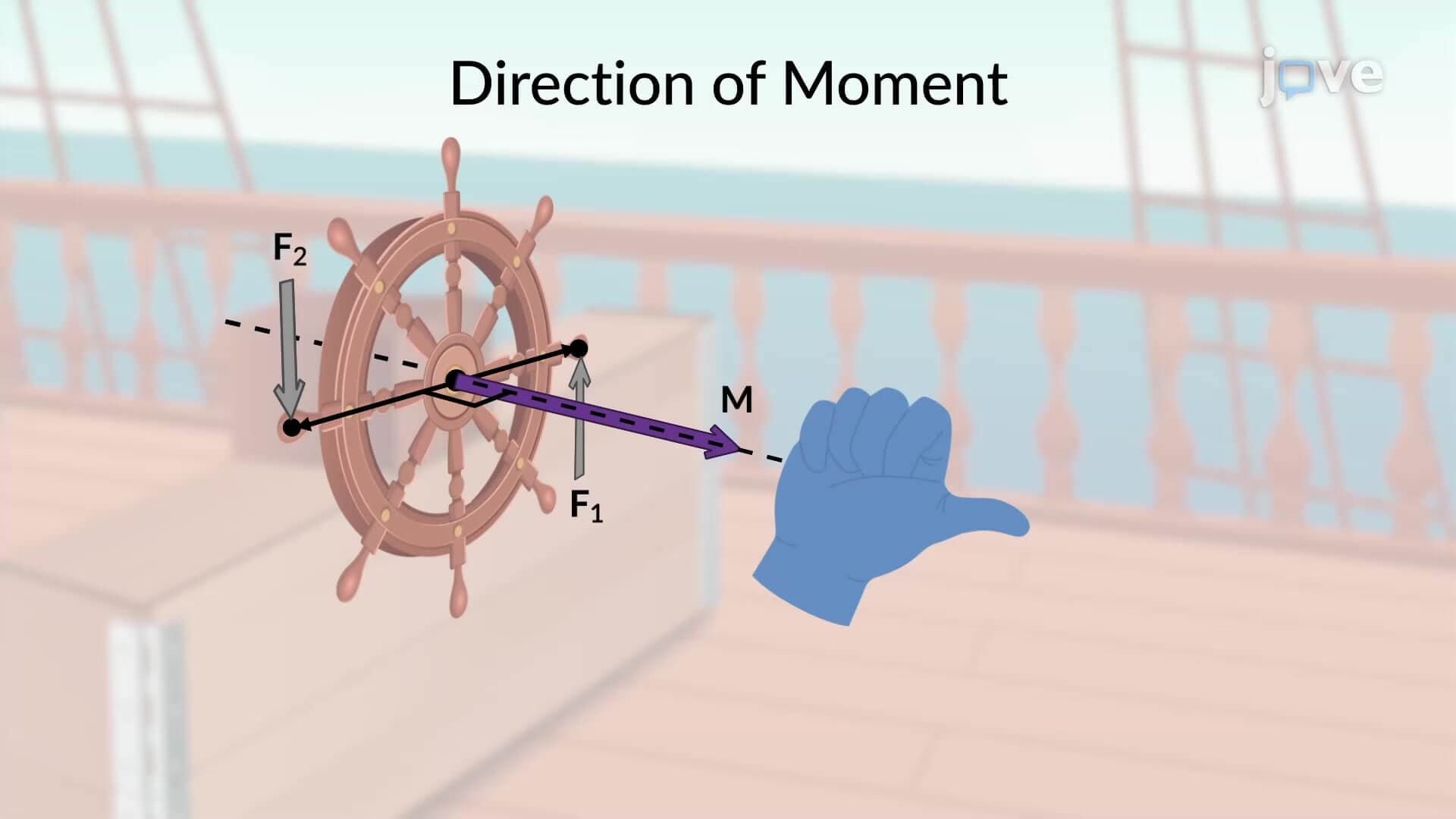
The foundation of this formulation rests on the principle that moments arise when forces act at distances from reference points, creating tendencies for objects to rotate. In vector form, each moment equals the cross product of the position vector (from reference point to force application point) and the force vector itself: M = r × F. This mathematical relationship ensures that moments possess both magnitude and direction, represented by vectors perpendicular to the plane containing the force and position vectors.
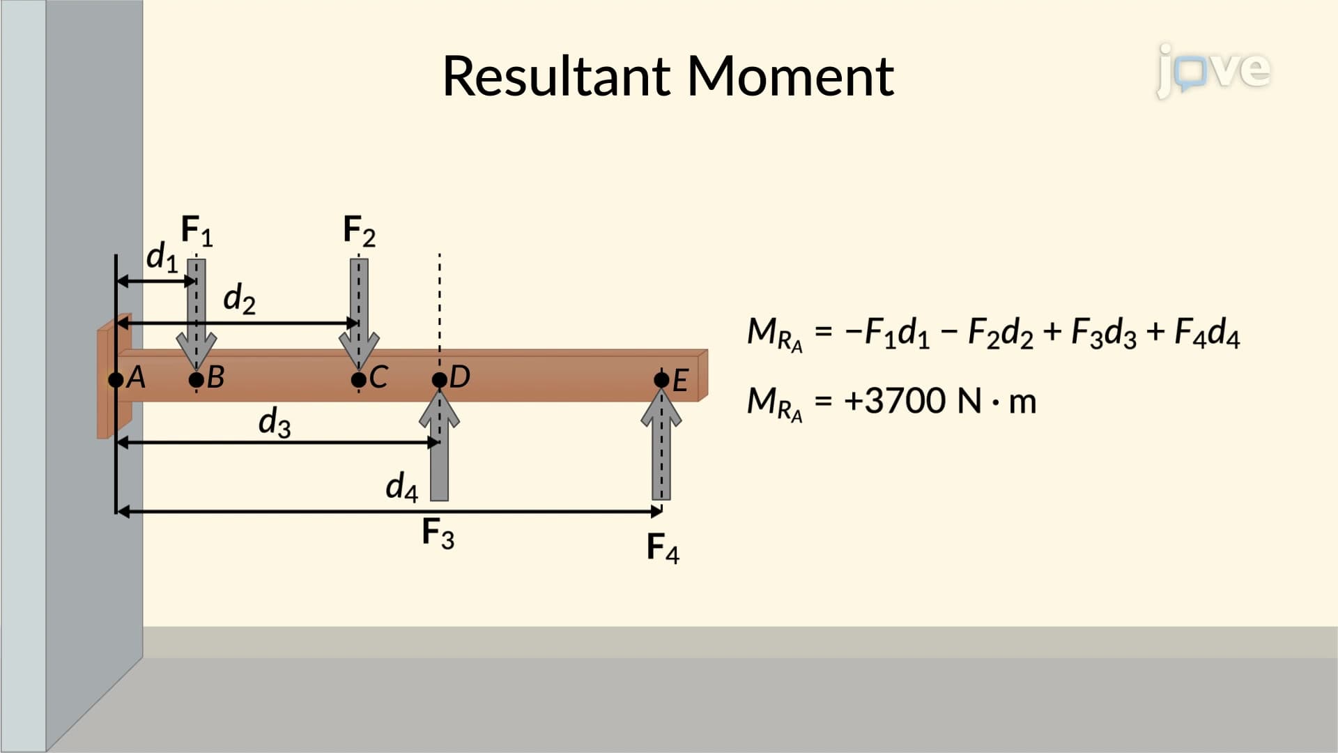
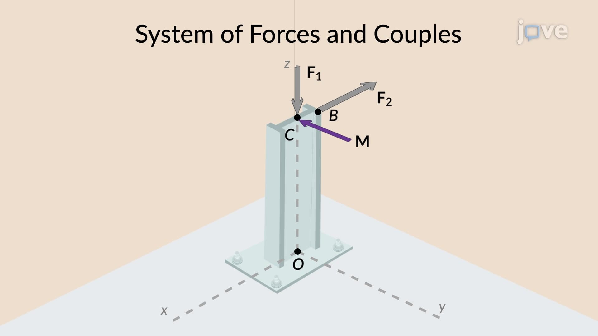
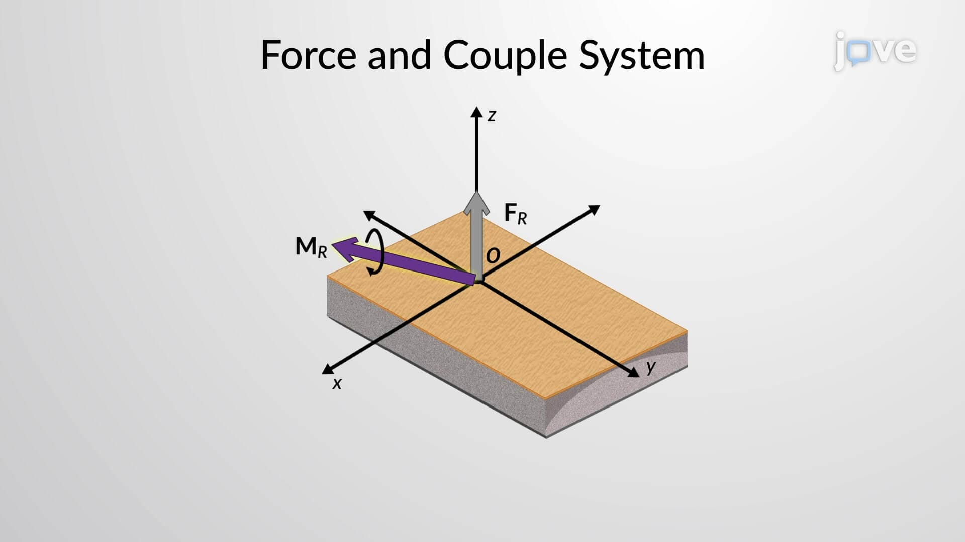
The power of resultant moment vector formulation becomes apparent when dealing with multiple forces acting simultaneously. Consider a telecommunications tower experiencing wind loads at different heights and directions. Engineers must calculate individual moments for each force, then vectorially sum these moments to determine the resultant moment: M(resultant) = M1 + M2 + M3 + ... + Mn.
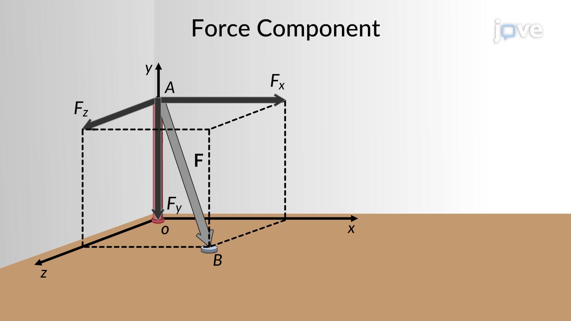
Each moment vector can be expressed in Cartesian form as M = Mx i + My j + Mz k, where i, j, and k represent unit vectors along the x, y, and z axes respectively. This representation allows engineers to systematically analyze complex loading scenarios using determinant expansions and cross-product mathematics. The determinant method provides a structured approach: M = |i j k; rx ry rz; Fx Fy Fz|, where r represents position vector components and F represents force vector components.
In structural engineering, resultant moment vector formulation enables analysis of building frameworks subjected to wind, seismic, and dead loads. For instance, when designing the support system for the Golden Gate Bridge, engineers calculated resultant moments from traffic loads, wind forces, and thermal expansion effects to ensure structural integrity. Similarly, mechanical engineers use this formulation when designing rotating machinery, analyzing gear systems, and evaluating bearing loads in automotive transmissions.
The concept frequently appears in standardized examinations including AP Physics C: Mechanics, where students encounter problems involving multiple forces creating moments about fixed points. College-level statics and dynamics courses extensively utilize resultant moment vector formulation for analyzing trusses, frames, and machine components. Students preparing for professional engineering licensing examinations encounter these concepts in structural analysis and mechanical design problems.
Mastering resultant moment vector formulation requires understanding reference point selection strategies. While the magnitude of resultant moments depends on reference point choice, the direction remains consistent for parallel force systems. This principle proves crucial when analyzing distributed loads on beams or calculating moments about different support points in structural systems.
Advanced applications include analyzing three-dimensional loading scenarios where forces act in multiple planes simultaneously. Aerospace engineers apply these principles when designing aircraft control surfaces, calculating moments about the center of gravity during flight maneuvers, and ensuring proper weight distribution for stable flight characteristics.
Frequently Asked Questions
Resultant moment vector formulation is a mathematical method that combines multiple moment vectors to determine the net rotational effect on an object, accounting for both magnitude and direction in three-dimensional space. Unlike scalar moments that only consider magnitude, vector formulation captures directional information through cross-product operations, making it essential for complex engineering analysis where spatial orientation matters.
AP Physics C exams typically present problems involving multiple forces acting on rigid bodies, requiring students to calculate individual moments using cross products and then vectorially sum them. Common scenarios include analyzing torques on rotating systems, determining equilibrium conditions for extended objects, and solving problems where forces act in multiple planes simultaneously.
You need solid foundations in vector algebra, including vector addition, cross products, and dot products, plus understanding of determinant calculations and Cartesian coordinate systems. Basic trigonometry and comfort with three-dimensional geometry also help, but these concepts are typically introduced gradually in physics and engineering courses, making them accessible to motivated high school students.
Civil engineers apply this concept when designing building foundations subjected to multiple load sources, analyzing bridge supports under traffic and wind loads, and calculating moments in high-rise buildings during earthquake conditions. For example, engineers designing the supports for the Space Needle in Seattle calculated resultant moments from wind loads, seismic forces, and structural weight to ensure stability.
Start with two-dimensional problems to build intuition, then progress to three-dimensional scenarios; practice identifying force application points and selecting appropriate reference points; work through problems systematically using the cross-product determinant method; and always verify your results by checking units and ensuring moment directions make physical sense.
Yes, this concept forms a cornerstone of engineering statics and dynamics courses, appearing extensively in mechanical engineering, civil engineering, and aerospace engineering curricula. It's essential for advanced courses in structural analysis, machine design, and fluid mechanics, making early mastery crucial for engineering success.
For objects in rotational equilibrium, the resultant moment vector must equal zero, meaning all moment components (Mx, My, Mz) sum to zero individually. This principle enables engineers to solve for unknown forces and design stable mechanical systems, forming the basis for analyzing everything from simple levers to complex robotic mechanisms.
Advanced applications include analyzing distributed loads using integration techniques, studying gyroscopic effects in rotating machinery, and applying moment principles to fluid mechanics problems involving rotating flows. These concepts also connect to advanced dynamics topics like angular momentum and three-dimensional rigid body motion analysis.
Related Micro-courses
Related Subjects
 Civil Engineering 30 micro-courses›Electrical Engineering 33 micro-courses›