Loading video…


 10 Concepts
 7.3K views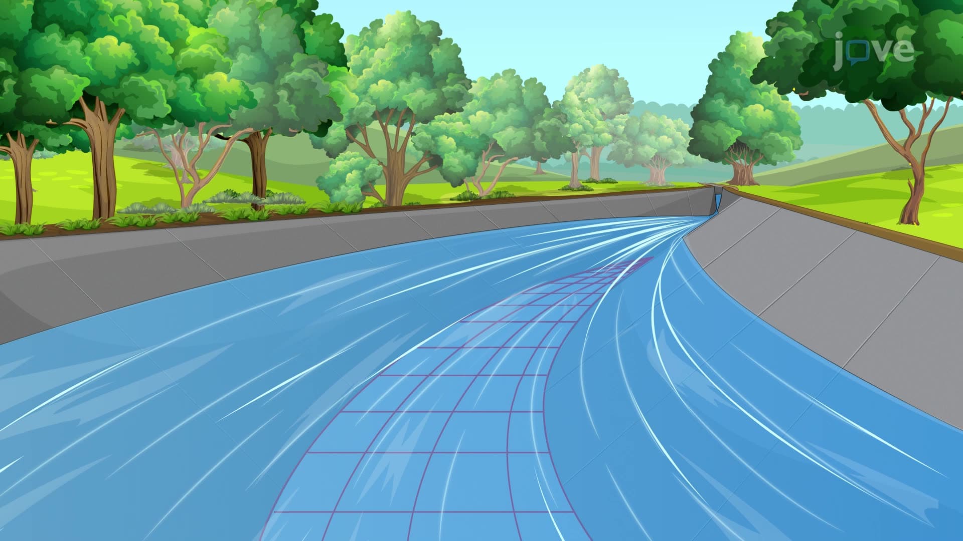

Video Summary: What are Plane Potential Flows
Ever wondered how engineers predict water flow around the Hoover Dam's spillways or design groundwater pumping systems across California's Central Valley? The Navier Stokes equations govern these complex fluid behaviors, but plane potential flows offer a simplified approach to understanding fluid motion patterns. These mathematical models assume irrotational and incompressible flow, using velocity potential and stream functions to describe everything from uniform channel flow to circular vortex patterns around drain systems. Watch the full video on JoVE Coach to master this concept with expert-led visuals and step-by-step explanations.
Plane potential flows represent a fundamental simplification of the complex Navier Stokes equations, making fluid dynamics accessible to engineering students and professionals. While the full Navier Stokes equations can describe virtually any fluid motion, they often require computational methods to solve. Plane potential flows offer an elegant analytical approach by assuming two key conditions: the flow is irrotational (no spinning motion of fluid particles) and incompressible (constant fluid density).
The types of Navier Stokes equations include the full viscous form, the inviscid Euler equations, and simplified potential flow equations. When we assume inviscid, irrotational flow, the Navier Stokes equations reduce to Laplace's equation: ∇²φ = 0, where φ represents the velocity potential function. This dramatic simplification occurs because viscous effects become negligible in many practical scenarios, such as flow around large structures or through porous media.
Students preparing for AP Physics C or college fluid mechanics courses will encounter this as a bridge between basic fluid statics and the full complexity of viscous flow. The Navier Stokes equations overview typically begins with these simplified cases to build intuition before tackling more complex scenarios.
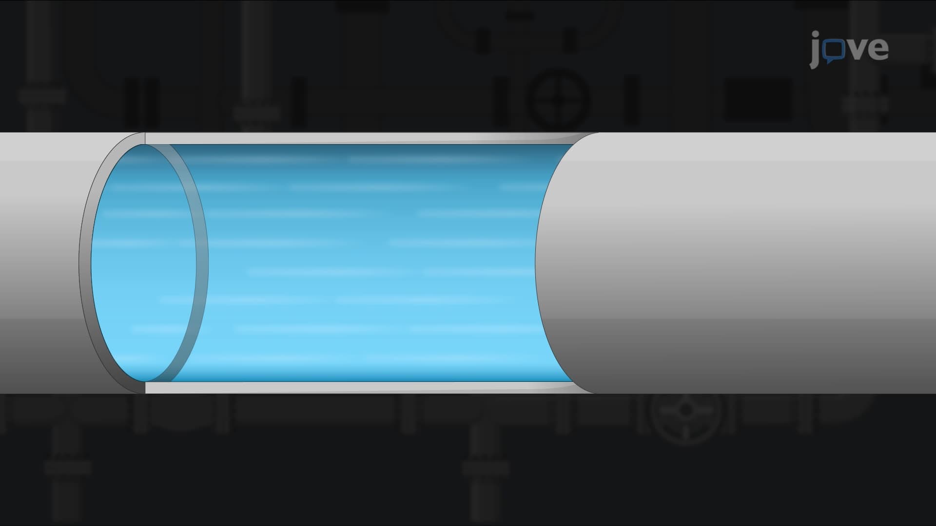
Consider the design of the spillway system at Glen Canyon Dam in Arizona. Engineers use uniform potential flow analysis to predict how water will behave as it moves through the straight approach channels. The parallel streamlines characteristic of uniform flow help determine optimal channel dimensions and flow capacities.
Source and sink flows find immediate application in groundwater management across the Ogallala Aquifer system. When agricultural wells pump water from underground, they create sink flow patterns that help hydrologists predict drawdown zones and interference between neighboring wells. California's Department of Water Resources routinely uses these models to manage groundwater sustainability.
Vortex flows become critical in designing urban stormwater management systems. The spiral flow patterns in drainage structures, from simple storm drains to complex detention basins, follow vortex flow principles. Engineers designing the flood control systems for Houston after Hurricane Harvey relied heavily on these flow pattern predictions.
Flow nets-the graphical representation combining streamlines and equipotential lines-serve as powerful design tools. The Army Corps of Engineers uses flow net analysis when designing levee systems along the Mississippi River. By predicting seepage paths under these structures, engineers can identify potential failure points and design appropriate countermeasures like cutoff walls or drainage systems.
This visualization technique proves invaluable for students tackling fluid mechanics problems on the FE exam or in undergraduate coursework. The ability to sketch and interpret flow nets bridges theoretical understanding with practical engineering judgment.
Related Micro-courses