Loading subject page…


10,864 views

Video Summary: What Is Impedances and Admittance
Ever wonder why your smartphone charger gets warm or why power lines use AC instead of DC? The answer lies in impedance combination - the fundamental way electrical components resist alternating current flow. Unlike simple DC resistance, impedance in AC circuits creates a complex dance between voltage and current, where inductors and capacitors behave completely differently at various frequencies. For instance, the wireless charging pad for your iPhone relies on precise impedance matching between coils to transfer energy efficiently. Watch the full video on JoVE Coach to master this concept with expert-led visuals and step-by-step explanations.
Impedance combination represents one of the most crucial concepts in alternating current (AC) circuit analysis. While DC circuits deal with simple resistance, AC circuits introduce the complex world of impedance, where the opposition to current flow depends not just on the material properties but also on frequency and the phase relationship between voltage and current.
The impedance combination definition becomes clear when examining how basic circuit elements behave across different frequencies. At DC (zero frequency), an inductor acts as a short circuit with zero impedance because it's essentially just a wire coil. Meanwhile, a capacitor behaves as an open circuit with infinite impedance since it cannot pass steady current. This explains why capacitors block DC in audio equipment and why inductors are used in DC power supply filtering.
However, at high frequencies, the roles reverse dramatically. Inductors become high-impedance elements, effectively blocking high-frequency signals - this principle is used in radio frequency (RF) chokes found in cell phone circuits. Capacitors, conversely, become low-impedance paths for high frequencies, which is why they're used as bypass capacitors in computer motherboards to filter high-frequency noise.
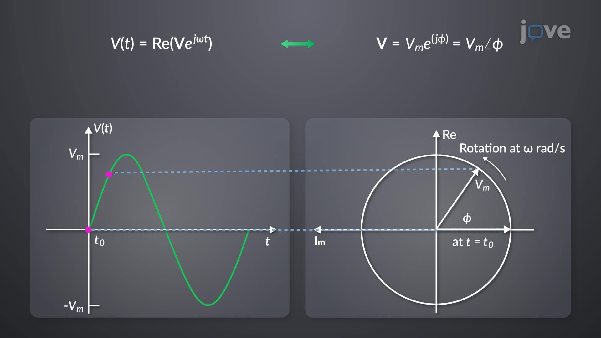
When exploring what is impedance combination in detail, we encounter two primary mathematical forms. In rectangular form, impedance Z = R + jX, where R represents resistance (real part) and X represents reactance (imaginary part). The reactance can be positive (inductive) or negative (capacitive), determining whether current lags or leads the applied voltage.
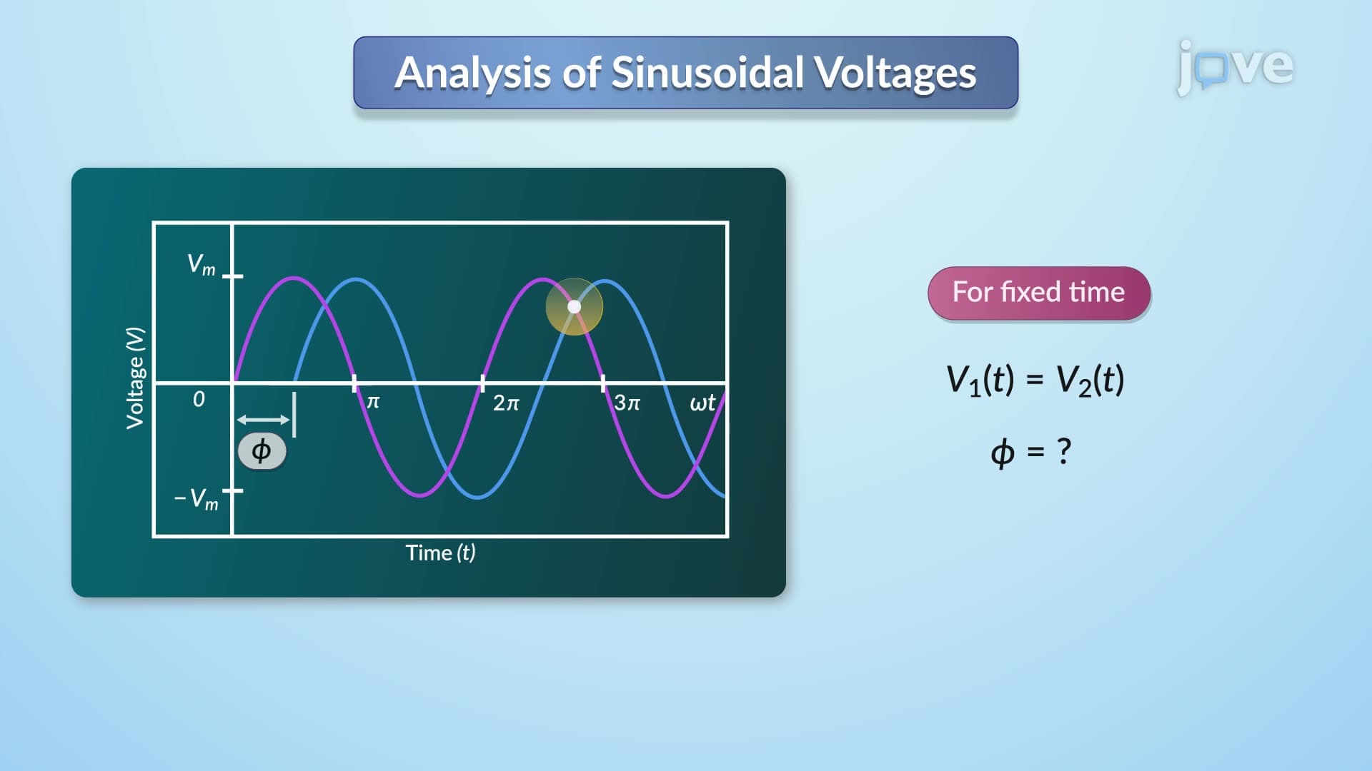
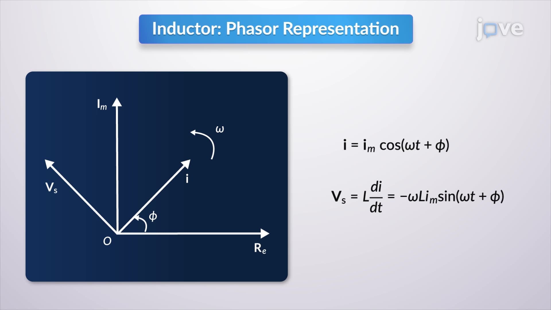
For AP Physics students and college electrical engineering courses, understanding this phase relationship is critical. In purely inductive circuits, current lags voltage by 90 degrees - imagine pushing a heavy door that doesn't respond immediately. In capacitive circuits, current leads voltage by 90 degrees - like a spring-loaded door that moves before you fully apply force.
The impedance combination concept appears frequently in standardized tests including AP Physics C, MCAT Physical Sciences, and college circuit analysis exams. Students often encounter problems involving impedance matching in transmission lines, resonance in LC circuits, and power factor calculations in electrical systems.
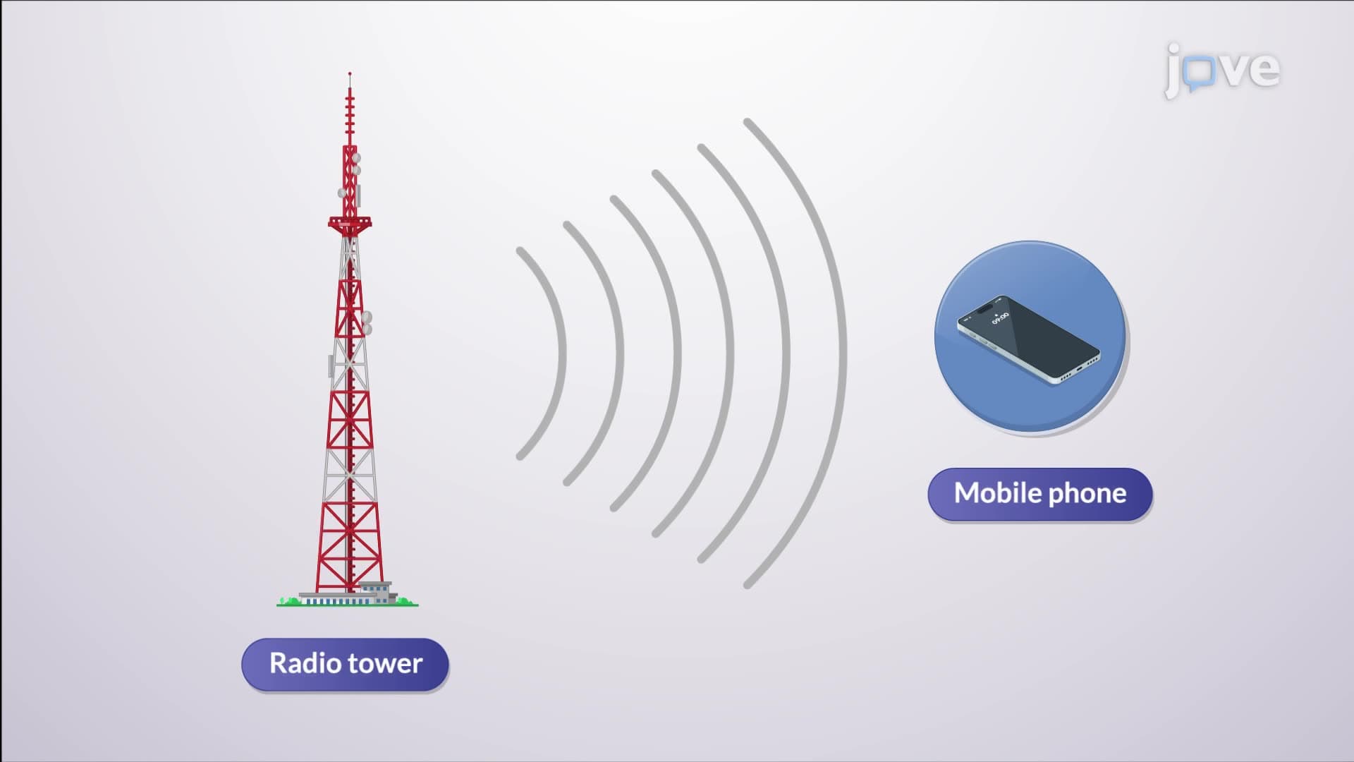
Real-world applications include impedance matching in audio equipment (why high-end speakers have specific ohm ratings), antenna design for cellular towers, and power transmission efficiency in the US electrical grid. Understanding admittance - the reciprocal of impedance - helps engineers design efficient power systems and explains why electrical utilities focus on power factor correction.
Related Micro-courses