Loading video…


 16 Concepts
 10.9K views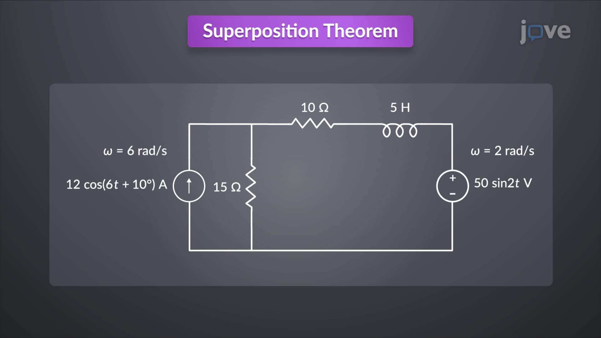

Video Summary: Superposition Theorem for Ac Circuits Explained
Ever wonder how engineers at Boeing design aircraft electrical systems that handle multiple AC power sources simultaneously? Op amp ac circuits using the Superposition Theorem For AC Circuits Explained demonstrate how complex multi-source systems can be analyzed by breaking them into manageable single-source problems. This powerful principle allows electrical engineers to predict circuit behavior in everything from smartphone chargers to hospital equipment across the United States. Watch the full video on JoVE Coach to master this concept with expert-led visuals and step-by-step explanations.
The superposition theorem represents one of the most fundamental analysis tools in electrical engineering, particularly when applied to AC circuits containing multiple independent sources. Unlike DC analysis where resistance remains constant, AC superposition requires careful consideration of frequency-dependent impedance, making it both more complex and more practically relevant to real-world applications.
When analyzing what are op amp ac circuits overview, the critical distinction from DC analysis lies in impedance variation. Capacitive reactance (XC = 1/(2πfC)) decreases with increasing frequency, while inductive reactance (XL = 2πfL) increases proportionally. This means that for each independent AC source operating at a different frequency, engineers must calculate entirely separate equivalent circuits with unique impedance values.
Consider a practical example: medical equipment manufacturers like GE Healthcare design patient monitoring systems using multiple AC signal sources. Each physiological signal (ECG at ~1Hz, EMG at ~100Hz) requires separate impedance calculations when these signals interact within the same amplifier circuit.
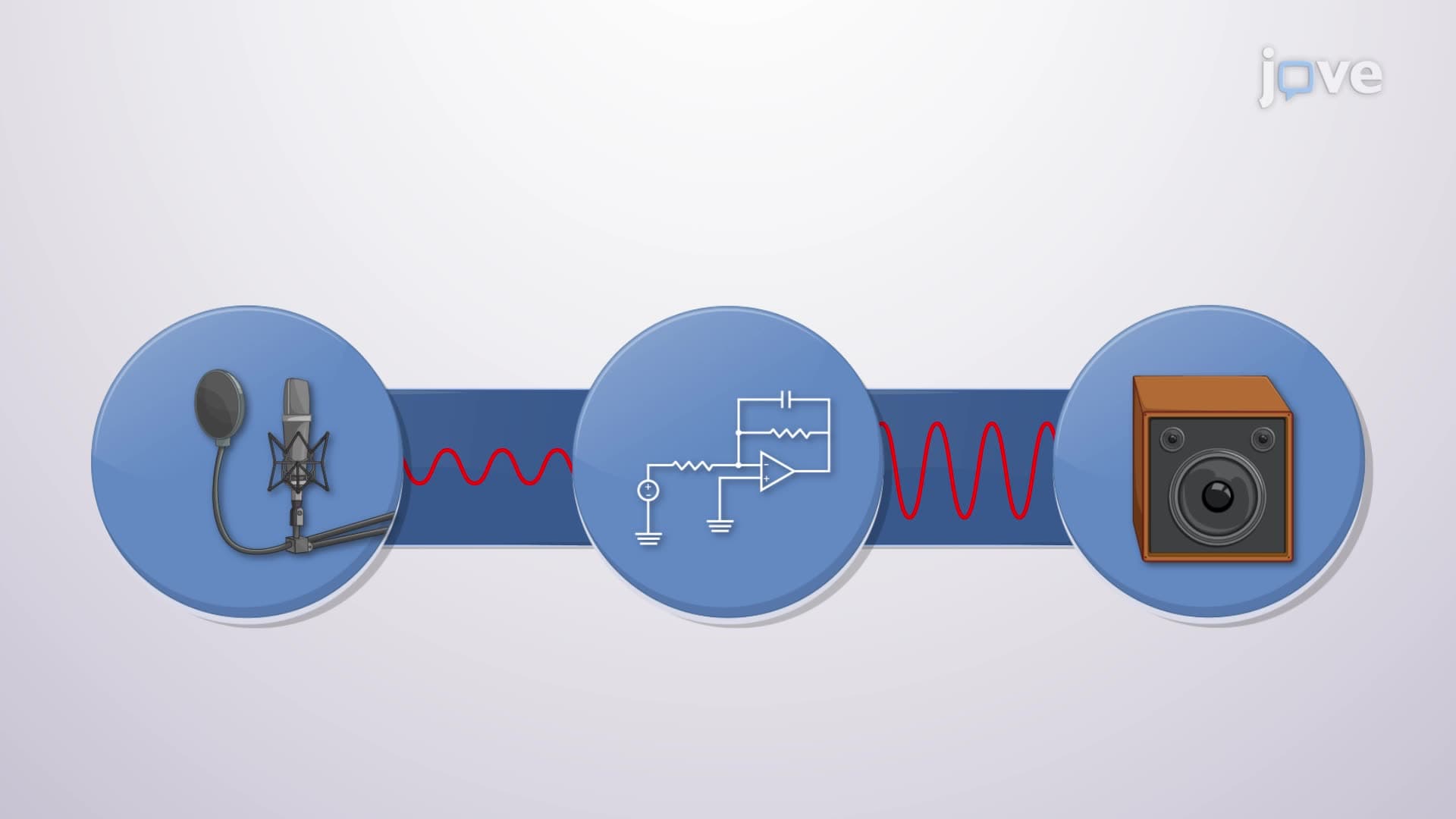
Major US corporations like Texas Instruments incorporate superposition principles into their op amp ac circuits design methodology. Power grid systems managed by companies like Duke Energy rely on superposition analysis to predict how multiple AC sources at 60Hz interact with harmonic frequencies generated by industrial equipment.
Students preparing for AP Physics C or college-level circuit analysis courses encounter superposition problems regularly. The NCEES Fundamentals of Engineering (FE) exam frequently tests this concept, particularly in questions involving power systems and signal processing applications.
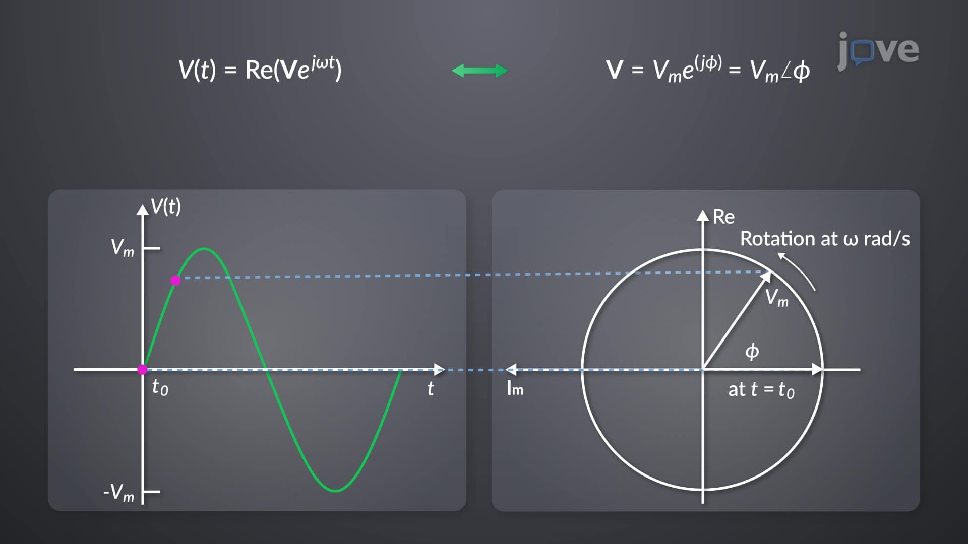
The mathematical beauty of superposition lies in its systematic approach: analyze each source independently, then algebraically sum the results. However, in AC circuits, this summation occurs in the time domain after converting each frequency-domain result back using inverse phasor transforms.
For engineering students at institutions like MIT or Georgia Tech, mastering this concept proves essential for advanced coursework in power systems, control theory, and communications. The non-sinusoidal output characteristic-where purely sinusoidal inputs produce complex waveforms-demonstrates the sophisticated behavior of linear systems under multi-frequency excitation.
Related Micro-courses