Loading video…


 16 Concepts
 10.9K views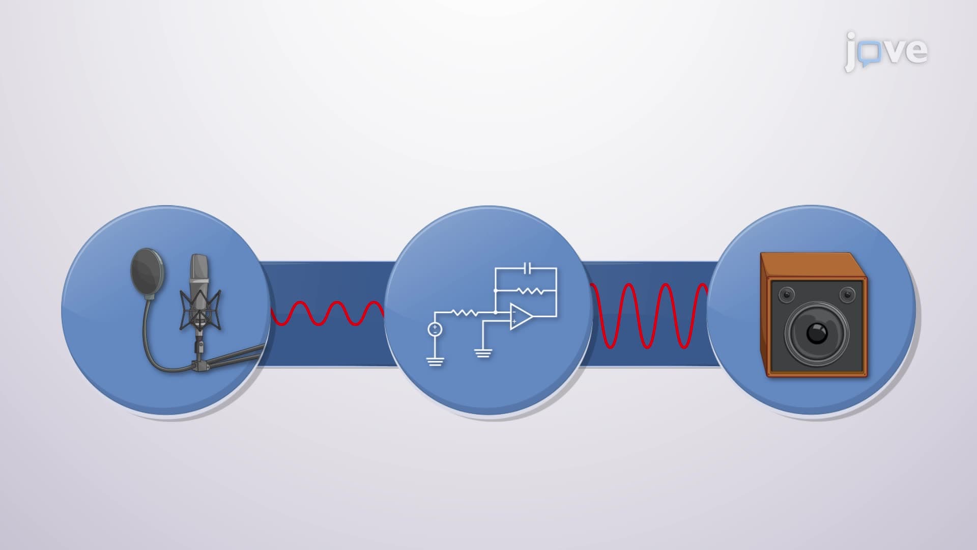

Video Summary: What are Op Amp Ac Circuits
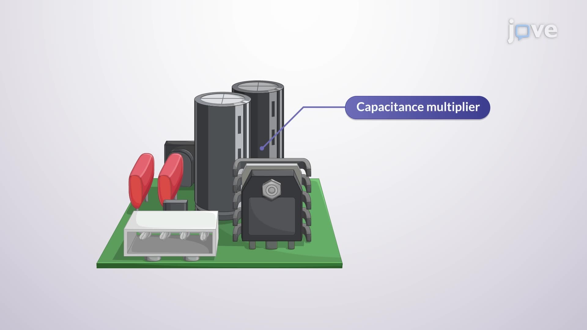
Did you know that the noise-canceling headphones used by air traffic controllers at LAX Airport rely on the same op amp AC circuit principles taught in high school physics? A design example capacitance multiplier circuit demonstrates how operational amplifiers process alternating current signals by combining resistors and capacitors in inverting configurations. These circuits form the backbone of audio filtering systems found in everything from smartphone speakers to professional recording studios across Nashville and Los Angeles. Watch the full video on JoVE Coach to master this concept with expert-led visuals and step-by-step explanations.
Op amp AC circuits represent fundamental building blocks in electronic signal processing, particularly valuable for students preparing for AP Physics exams and college-level electrical engineering courses. Unlike DC circuits that deal with constant voltages, these circuits process time-varying signals using operational amplifiers combined with reactive components like capacitors and inductors.
A design example capacitance multiplier circuit tutorial typically begins with the inverting amplifier configuration, where the operational amplifier's negative input receives the signal through a resistor R1, while the positive input connects to ground. The feedback path contains both resistor R2 and capacitor C1 in parallel, creating a frequency-dependent impedance that determines the circuit's filtering characteristics. This configuration appears frequently in MCAT physics sections and college circuit analysis exams.
Understanding design example capacitance multiplier circuit basics requires mastering impedance calculations. The capacitor's impedance equals 1/(jωC), where ω represents angular frequency (2πf) and j indicates the imaginary unit. Students at institutions like MIT and UC Berkeley learn that this frequency dependence allows the circuit to behave differently at various frequencies, making it ideal for audio applications.
The design example capacitance multiplier circuit concept operates through impedance division principles. When analyzing how design example capacitance multiplier circuit works, the key insight involves recognizing that Z2 (the feedback impedance) equals the parallel combination of R2 and the capacitor's impedance. At low frequencies, the capacitor's high impedance means R2 dominates, while at high frequencies, the capacitor's low impedance takes precedence.
Real-world applications include the pre-amplifiers used in recording studios at Abbey Road Studios' Nashville location, where engineers rely on these circuits to filter unwanted low-frequency rumble from microphone signals. Similarly, the hearing aids manufactured by companies like Phonak in their US facilities employ similar op amp AC circuits to enhance speech frequencies while attenuating background noise.
For students preparing for standardized exams, this design example capacitance multiplier circuit overview connects to broader topics in AC circuit analysis. College physics courses at schools like Stanford and Carnegie Mellon emphasize the mathematical relationship: Vout/Vin = -Z2/Z1, where the negative sign indicates phase inversion typical of inverting amplifiers. This equation appears regularly on midterm exams and serves as the foundation for more complex filter designs used in industries ranging from telecommunications to biomedical instrumentation.
Related Micro-courses