Loading video…


 16 Concepts
 10.9K views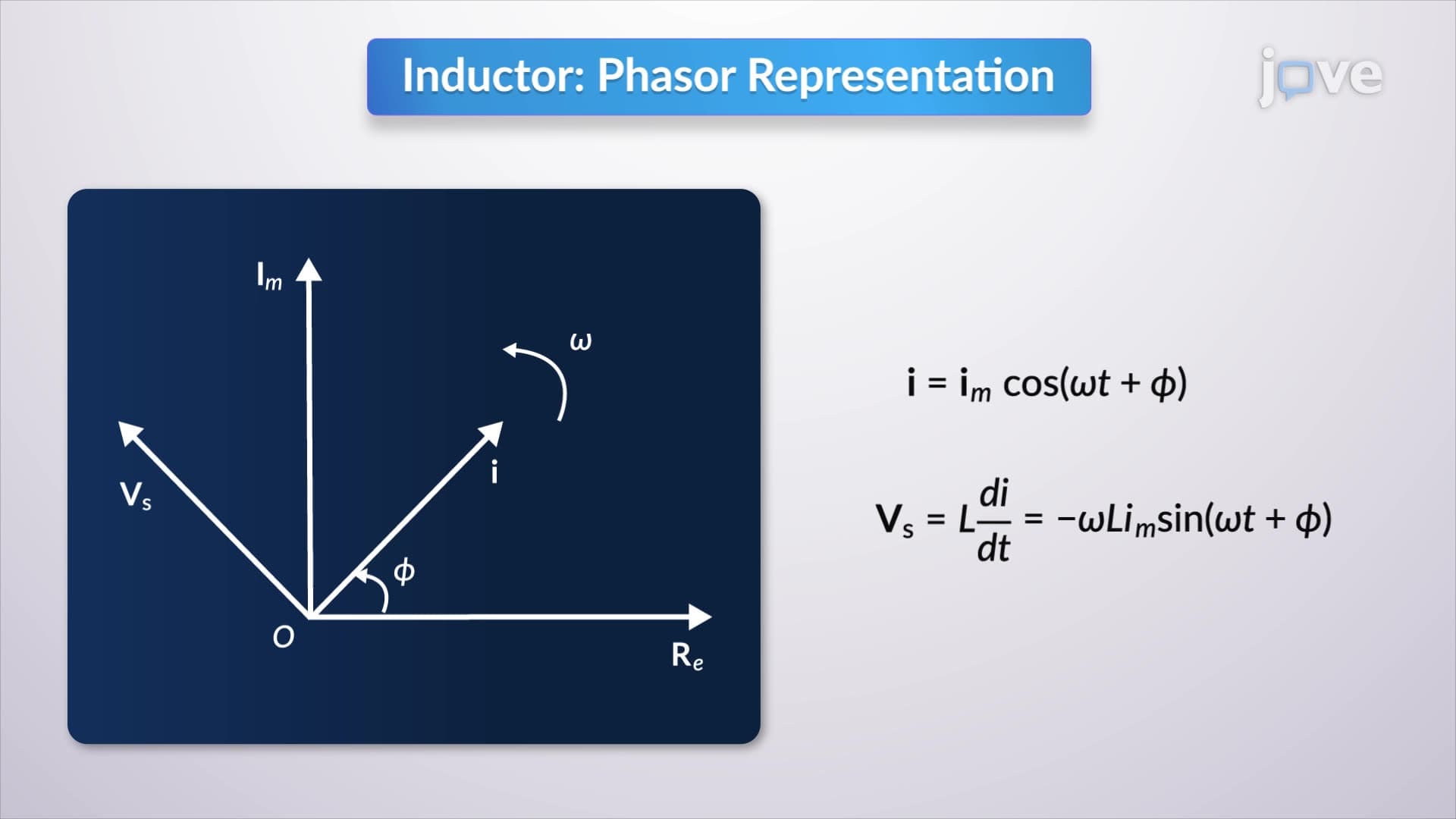

Video Summary: Phasor Relationships for Circuit Elements Explained
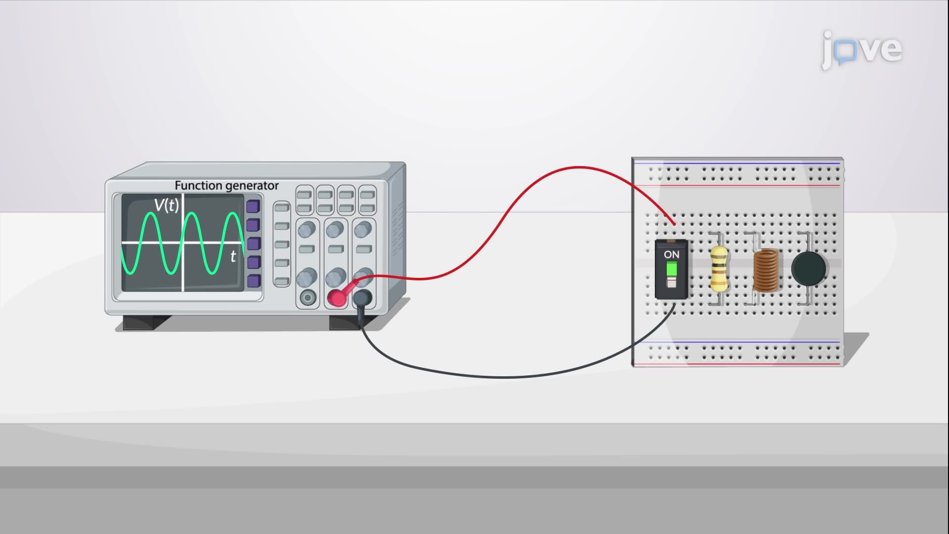
Ever wonder how electrical engineers design power grids that keep your smartphone charged 24/7? Understanding kirchoff's laws using phasors is the key to analyzing complex AC circuits that power everything from your home to Tesla's Supercharger stations across America. Phasor relationships for circuit elements explained reveals how resistors, inductors, and capacitors behave differently in AC circuits, transforming time-domain voltage and current into manageable frequency-domain representations. Watch the full video on JoVE Coach to master this concept with expert-led visuals and step-by-step explanations.
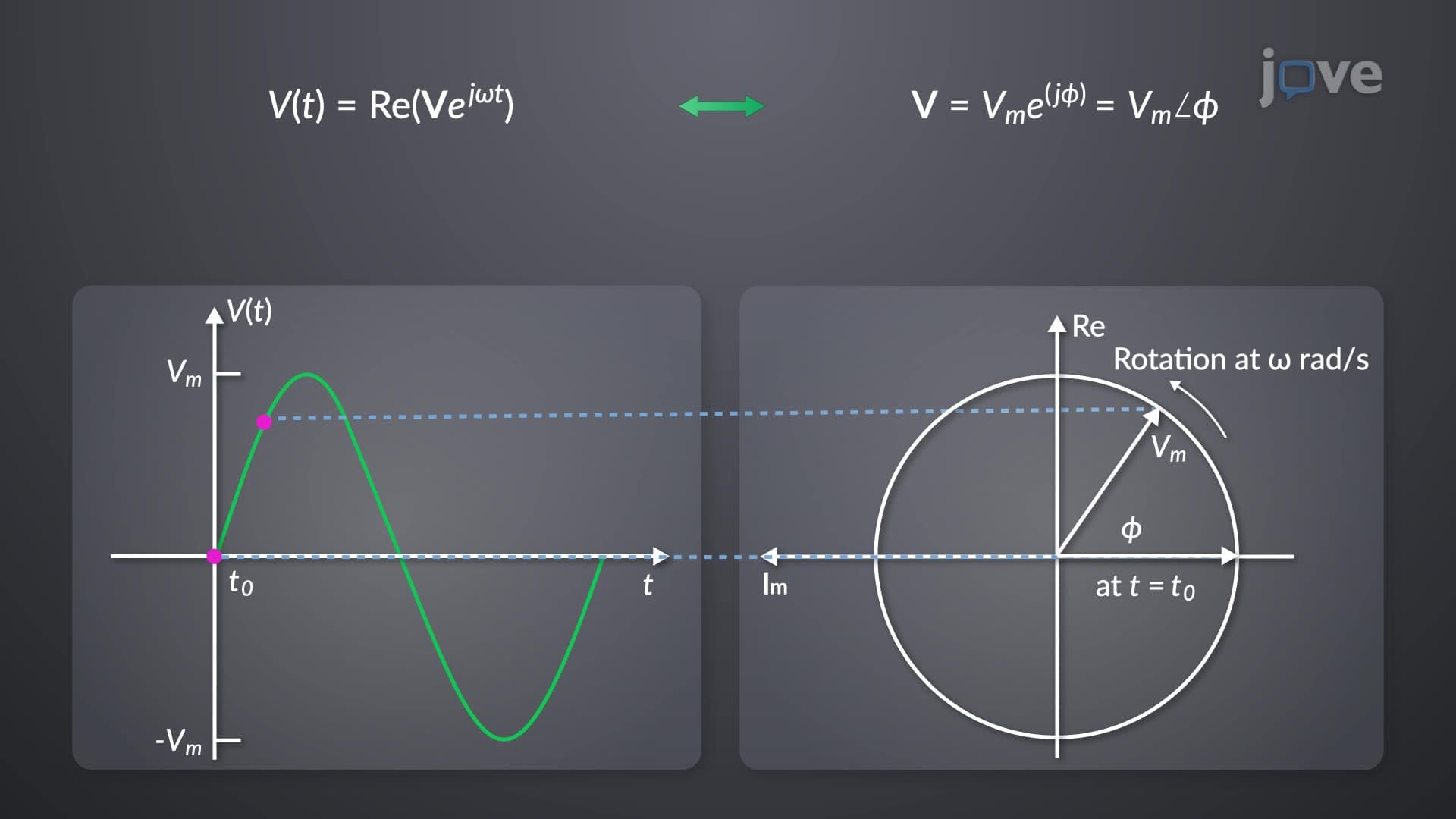
Phasor analysis revolutionizes how we understand AC circuits by converting complex time-varying sinusoidal functions into simple algebraic expressions. This mathematical transformation is essential for electrical engineering students preparing for AP Physics C, college-level circuit analysis courses, and professional engineering exams.
In resistive circuits, voltage and current maintain a direct, in-phase relationship regardless of whether we're working in time or frequency domain. Ohm's law (V = IR) applies identically in both domains, making resistors the simplest elements to analyze. This concept frequently appears on AP Physics C exams and forms the baseline for understanding more complex reactive elements.
For practical applications, consider the heating elements in electric ovens manufactured by companies like GE or Whirlpool. These resistive loads consume power continuously, with voltage and current always synchronized, making them ideal for steady-state power calculations.
Inductors create a fascinating phase shift where current lags voltage by exactly 90 degrees. This relationship stems from the fundamental property that voltage across an inductor equals L(di/dt). When we transform this time-domain derivative into phasor notation, we get the impedance ZL = jωL, where j represents the 90-degree phase shift.
This concept is crucial for understanding power transmission systems used by utilities like Pacific Gas & Electric or ConEd. Large transformers and transmission lines exhibit significant inductive properties, requiring careful phase management to maintain grid stability.
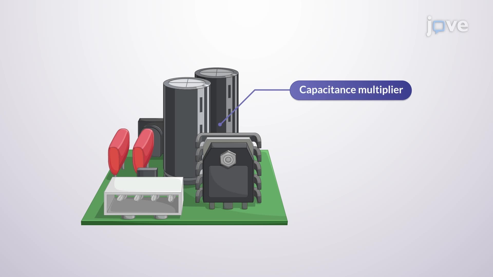
Capacitors exhibit the opposite behavior to inductors, current leads voltage by 90 degrees. The fundamental relationship i = C(dv/dt) transforms into the impedance ZC = 1/(jωC) in phasor form. This negative phase shift has profound implications for power factor correction in industrial applications.
Modern electric vehicle charging stations, like those manufactured by ChargePoint across US highways, incorporate capacitive elements for power factor correction, ensuring efficient energy transfer while meeting utility company requirements for reactive power management.
Related Micro-courses