Loading subject page…
- Electrical Engineering
- Diagrams and Signal Flow Graphs
Electrical Engineering
All Micro-courses:33

1.
Basics of Electric Circuits
13 Concepts
2.
DC Circuit Analysis
11 Concepts
3.
Operational Amplifiers
9 Concepts
4.
Energy Storage Elements
8 Concepts
5.
First and Second-Order Circuits
13 Concepts
6.
AC Circuit Analysis
16 Concepts
7.
AC Steady State Power
9 Concepts
8.
Three-Phase Circuits
11 Concepts
9.
Frequency Response
15 Concepts
10.
Basics of Semiconductors
11 Concepts
11.
Diodes
14 Concepts
12.
Transistors
20 Concepts
13.
Introduction to Signals and Systems
11 Concepts
14.
Linear Time- Invariant Systems
7 Concepts
15.
The Laplace Transform
5 Concepts
16.
Fourier Series
7 Concepts
17.
The Fourier Transform
10 Concepts
18.
Sampling
7 Concepts
19.
z-Transform
7 Concepts
20.
Introduction to Control Systems
5 Concepts
21.
Modeling in Time and Frequency Domain
9 Concepts
22.
Diagrams and Signal Flow Graphs
7 Concepts
23.
Transient and Steady-state Response Analysis
7 Concepts
24.
Root-Locus Method
7 Concepts
25.
Design of Control Systems
10 Concepts
26.
Power Transformers
4 Concepts
27.
Transmission Line Parameters
7 Concepts
28.
Steady-State Transmission Lines and Power Flows
6 Concepts
29.
Symmetrical and Unsymmetrical Faults
8 Concepts
30.
System Protection
9 Concepts
31.
Transient Stability and System Controls
7 Concepts
32.
Transmission Lines: Transient Operation
5 Concepts
33.
Power Distributions
5 Concepts
Diagrams and Signal Flow Graphs
 7 Concepts
 4.8K Views
 Popular topics
Concepts: 7
01:25
448 views
01:20
2.5K views
01:22
359 views

01:22
227 views
01:20
675 views
01:18
398 views
01:16
202 views
Block diagrams and signal flow graphs are essential tools for analyzing and designing control systems, from automotive cruise control to aircraft flight controls. These visual representations help engineers model system behavior, calculate transfer functions, and understand feedback mechanisms. This comprehensive course covers block diagram elements, reduction techniques, Mason's gain formula, and signal flow graph algebra, providing students with foundational skills used throughout American engineering programs and validated by JoVE Coach methodology.
- Understand the fundamental elements of block diagrams including comparators, transfer function blocks, and feedback loops
- Learn to convert mathematical equations into visual block diagram representations for system analysis
- Identify and apply block diagram reduction techniques to simplify complex control system models
- Explore multi-input and multi-variable systems commonly found in automotive and aerospace applications
- Analyze signal flow graphs as an alternative representation method for control systems
- Apply Mason's gain formula to calculate transfer functions from signal flow graphs
- Understand signal flow graph algebra rules for parallel branches, cascaded connections, and feedback loops
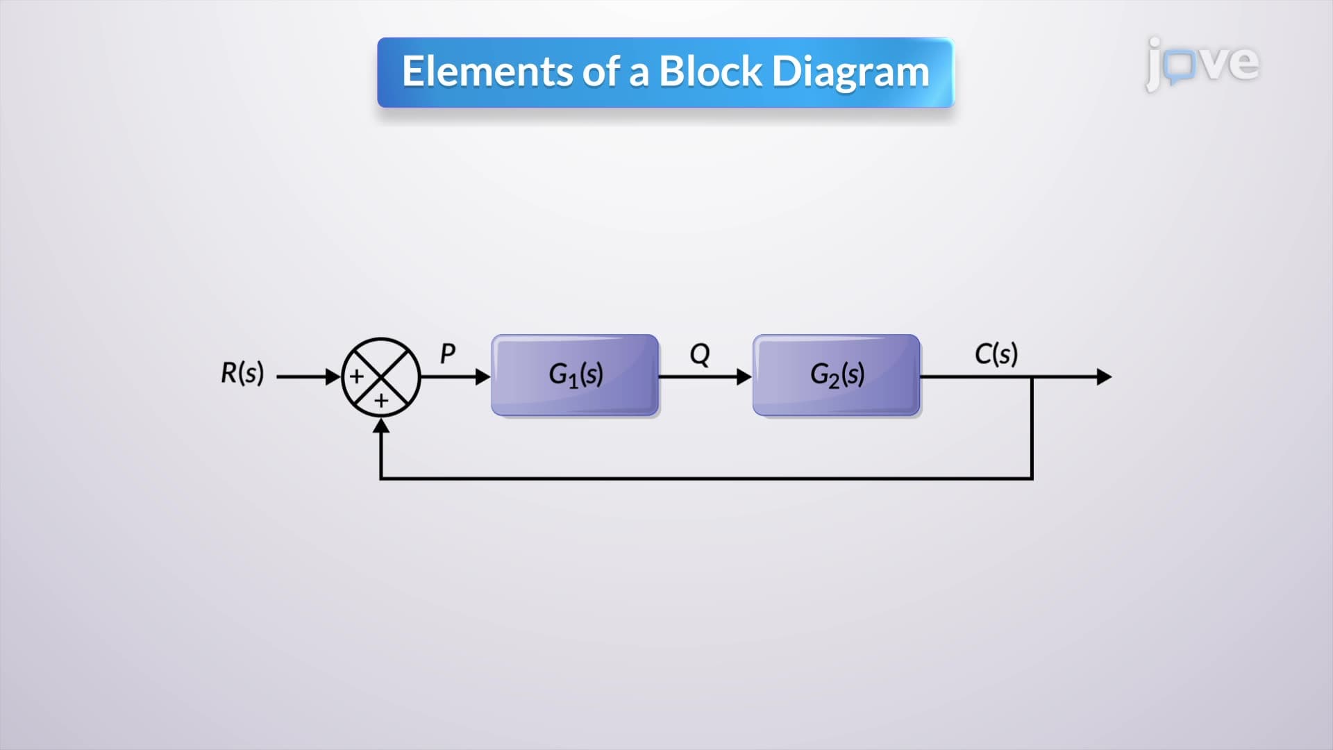
1. Block Diagram Fundamentals and Elements Block diagrams serve as visual representations of system input-output relationships, essential for analyzing everything from home heating systems to industrial automation. Key components include comparators that perform mathematical operations like addition and subtraction, transfer function blocks representing system equations in Laplace or time domains, and feedback loops that enable error correction. In American automotive systems like cruise control, these elements work together where the desired speed input is compared with actual speed, generating error signals that activate throttle actuators to maintain constant velocity.
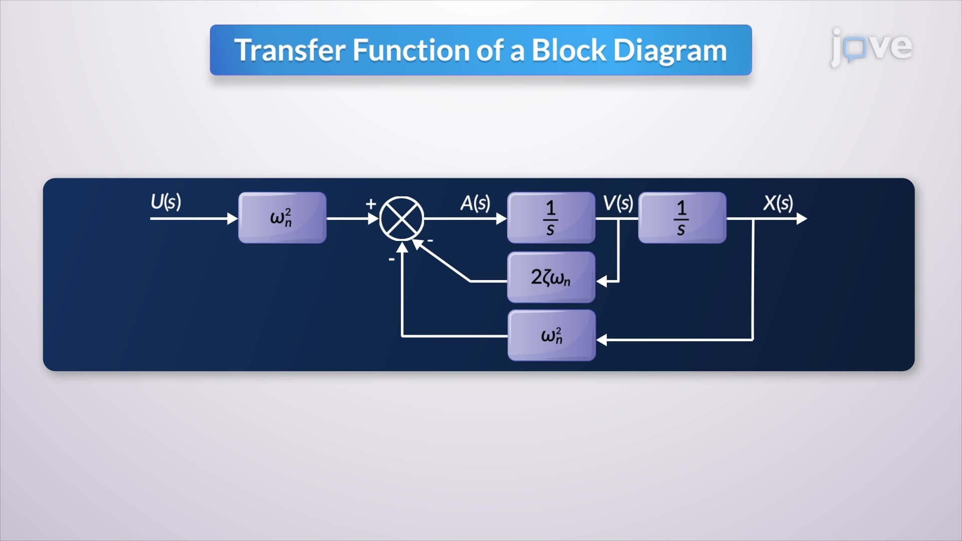
2. Mathematical Equation to Block Diagram Conversion Converting differential equations into block diagrams involves systematic transformation using Laplace domain techniques under zero initial conditions. For a spring-mass-damper system commonly studied in American physics courses, the second-order differential equation is rearranged to isolate output variables, then interpreted as signals flowing through specific transfer function blocks. The integration operation (1/s in Laplace domain) connects acceleration to velocity to displacement, creating a visual representation that engineering students can manipulate more easily than complex mathematical expressions.
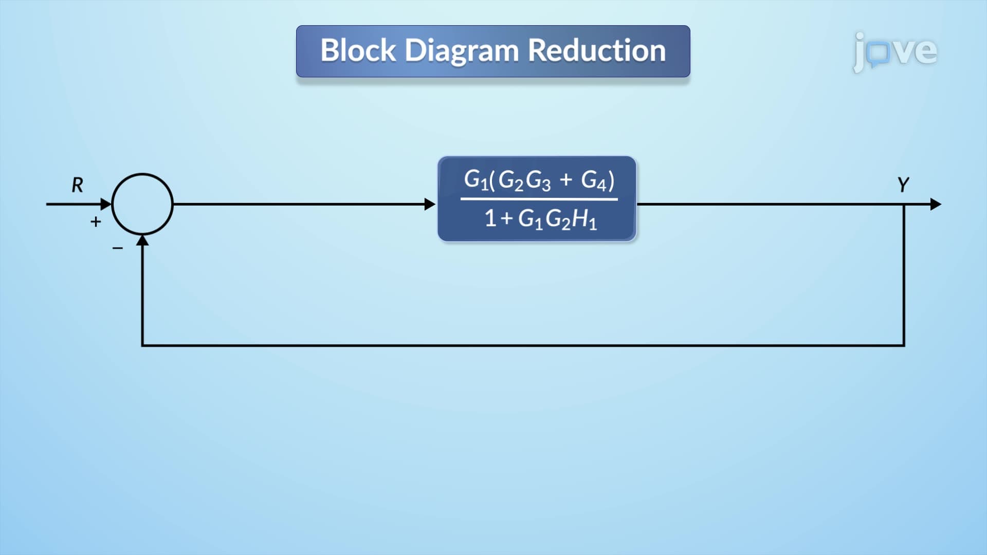
3. Block Diagram Reduction Techniques and Simplification Systematic reduction methods transform complex multi-loop systems into single equivalent transfer functions through strategic manipulation of branch points and comparators. The process involves relocating connection points without altering mathematical relationships, combining series and parallel blocks, and eliminating internal feedback loops. American engineering curricula emphasize these techniques because they enable students to analyze complex systems like aircraft flight controls or manufacturing process controllers by reducing them to manageable single-block representations while preserving all essential dynamic characteristics.
4. Multi-Input and Multi-Variable System Analysis Real-world systems like commercial aircraft or industrial plants involve multiple inputs affecting multiple outputs simultaneously, requiring matrix-based analysis methods. Cruise control systems demonstrate multi-input behavior by responding to both driver speed commands and external disturbances like uphill grades. The superposition principle allows engineers to analyze each input separately, then combine responses to predict overall system behavior. American aerospace applications exemplify multi-variable systems where pilot control inputs affect aircraft pitch, roll, and yaw through interconnected transfer function matrices.
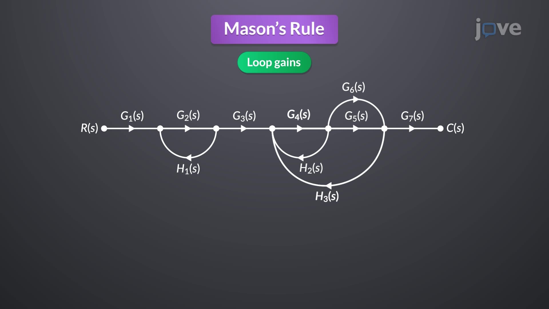
5. Mason's Gain Formula and Transfer Function Calculation Mason's rule provides a systematic method for calculating transfer functions directly from signal flow graphs without requiring block diagram reduction. The formula incorporates forward-path gains (products of gains along paths from input to output), loop gains (products of gains around closed loops), and non-touching loop combinations. Delta calculations involve alternating series considering all loop interactions, while Delta_k excludes loops intersecting specific forward paths. This technique proves invaluable for analyzing complex feedback systems common in American industrial automation and spacecraft guidance systems.
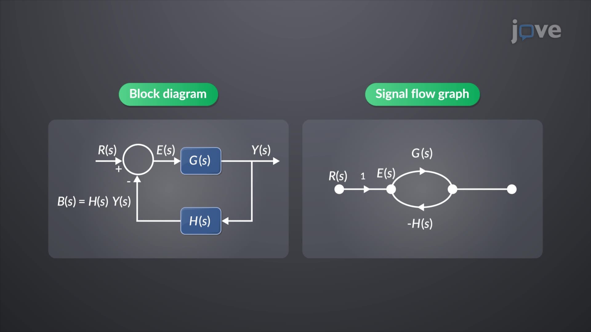
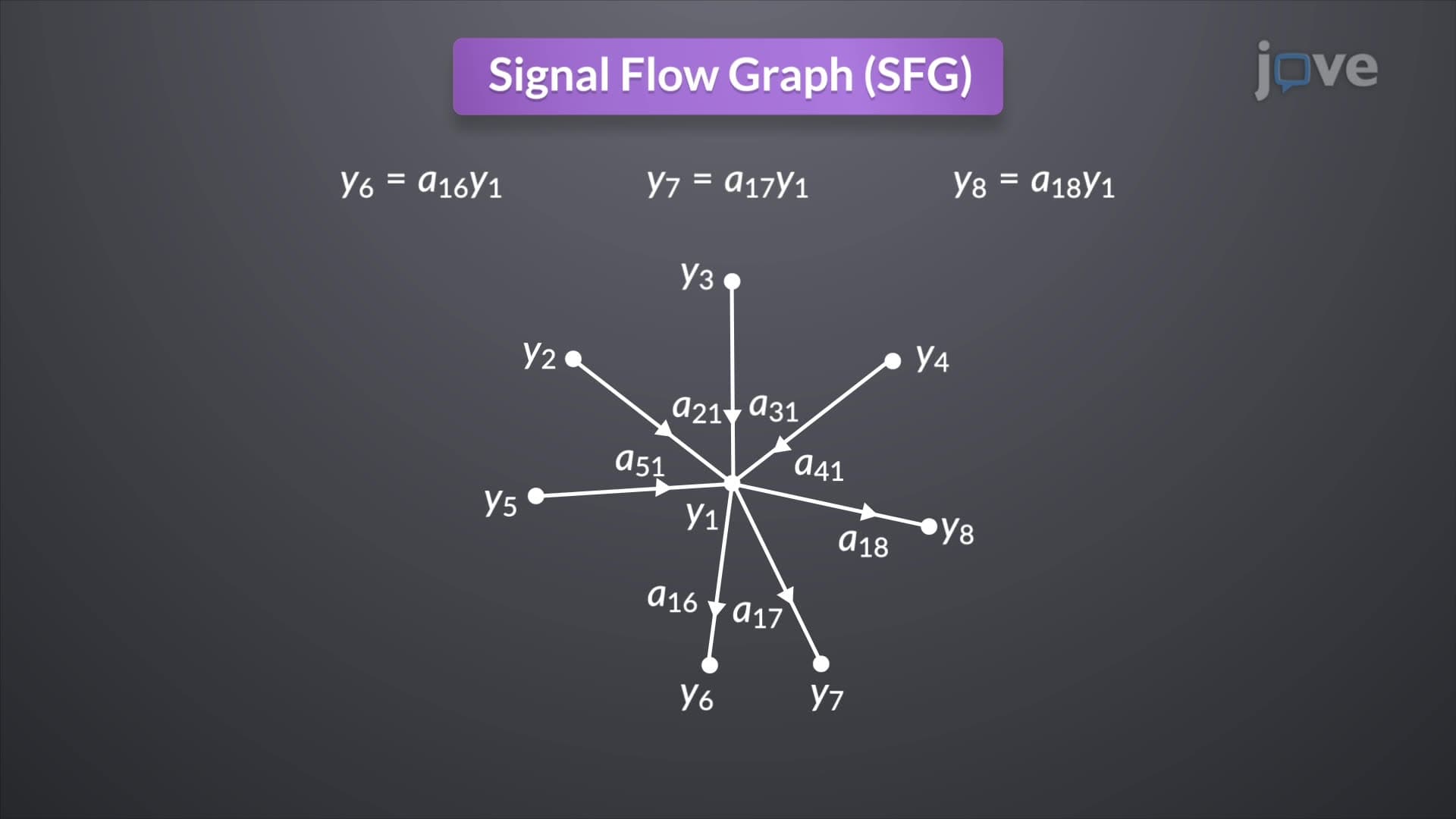
6. Signal Flow Graph Construction and Algebra Signal flow graphs offer an alternative to block diagrams using nodes to represent signals and directed branches to show transfer functions between variables. Unlike block diagrams where negative signs appear at summing junctions, signal flow graphs incorporate signs directly into branch gains. Construction involves identifying all system variables, creating corresponding nodes, and connecting them with appropriately labeled branches. Algebraic manipulation rules allow combining parallel branches (sum of gains) and cascaded branches (product of gains), enabling systematic simplification of complex interconnected systems found in modern American manufacturing and aerospace applications.