Loading video…


 13 Concepts
 38.6K views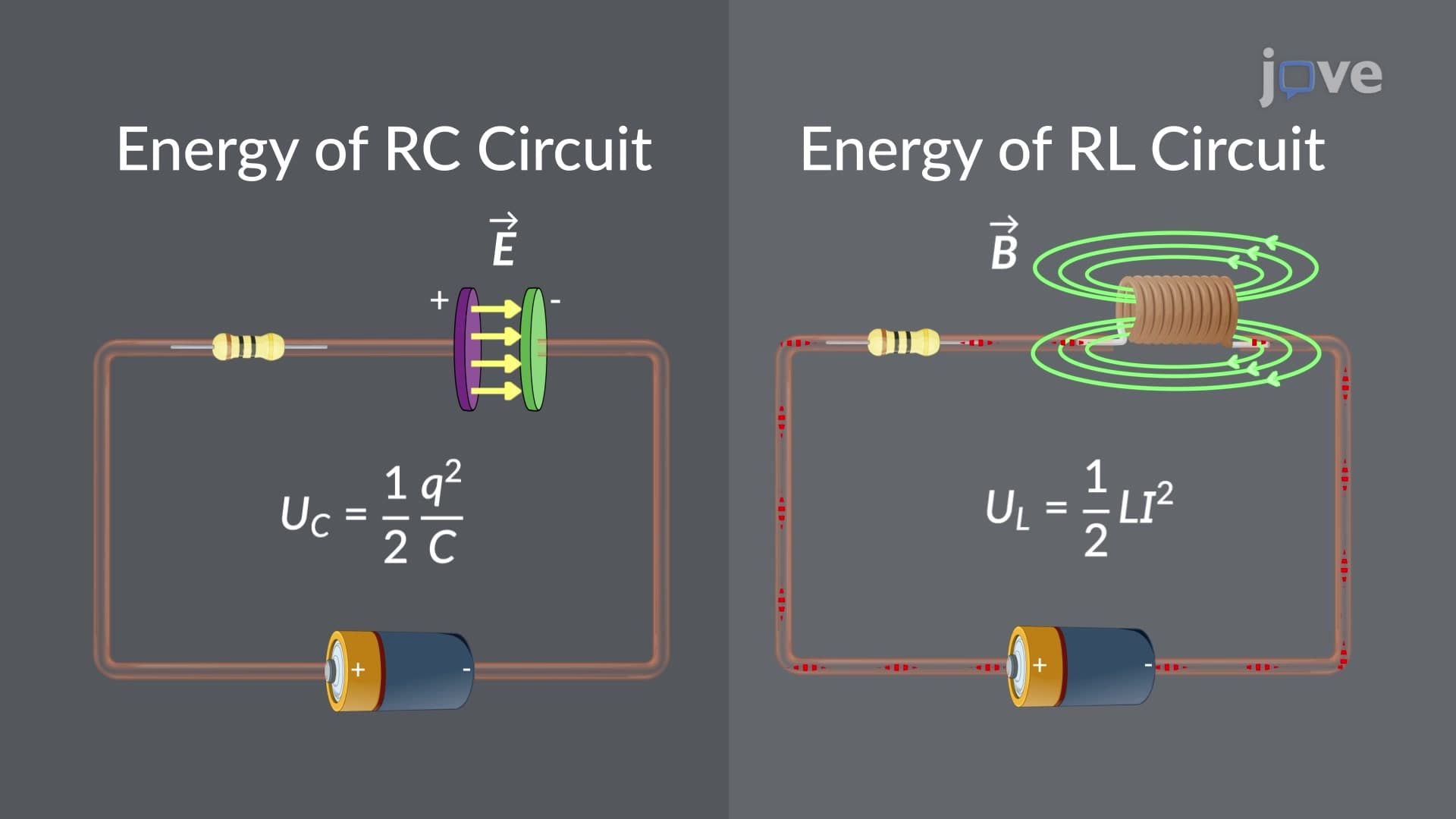

Video Summary: Comparison Between Rl and Rc Circuits Explained
Ever wondered why your smartphone camera flash charges up slowly but fires instantly? The comparison between RL and RC circuits explains this fascinating electrical behavior that powers countless devices from cardiac pacemakers to Tesla's electric vehicle systems. While RC circuits combine resistors with capacitors to store electric field energy, RL circuits pair resistors with inductors to harness magnetic fields. Watch the full video on JoVE Coach to master this concept with expert-led visuals and step-by-step explanations.
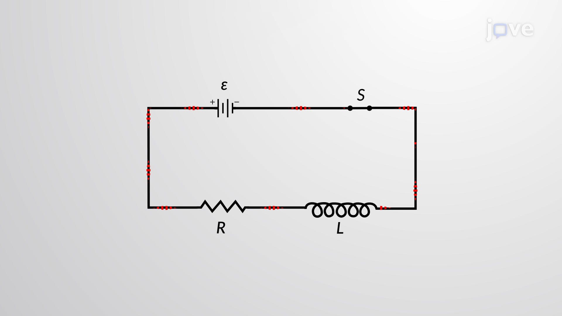
The comparison between RL and RC circuits reveals fundamental principles that govern modern electronics. These circuits represent two distinct approaches to combining energy storage components with resistive elements, each serving unique purposes in electrical engineering applications.
RC circuits demonstrate counterintuitive current behavior that surprises many students. When initially connected to a battery, the uncharged capacitor acts like a short circuit, allowing maximum current flow. This explains why camera flash units can draw significant power during charging. As the capacitor accumulates charge, it increasingly opposes current flow until reaching full charge when current drops to zero.
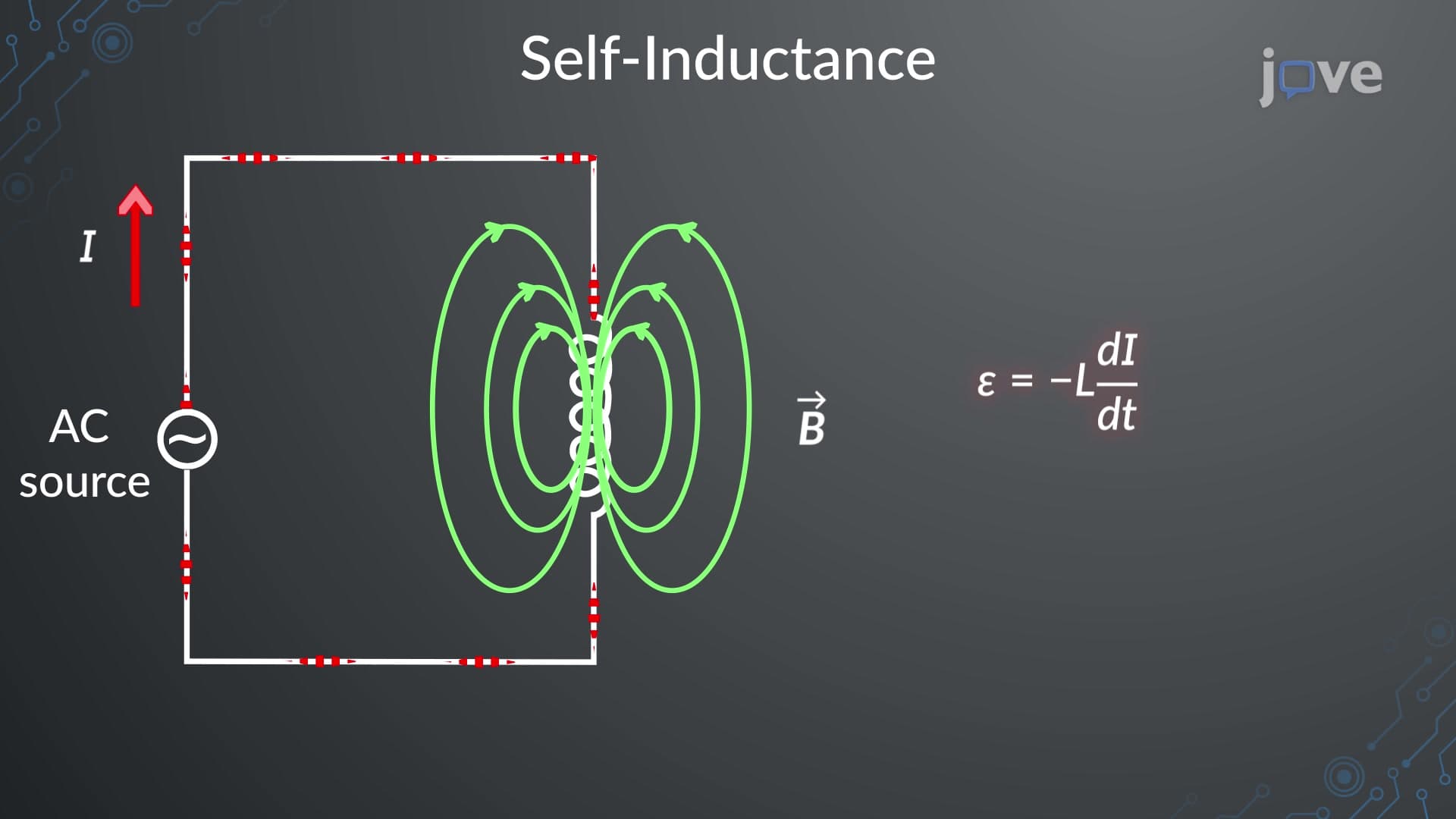
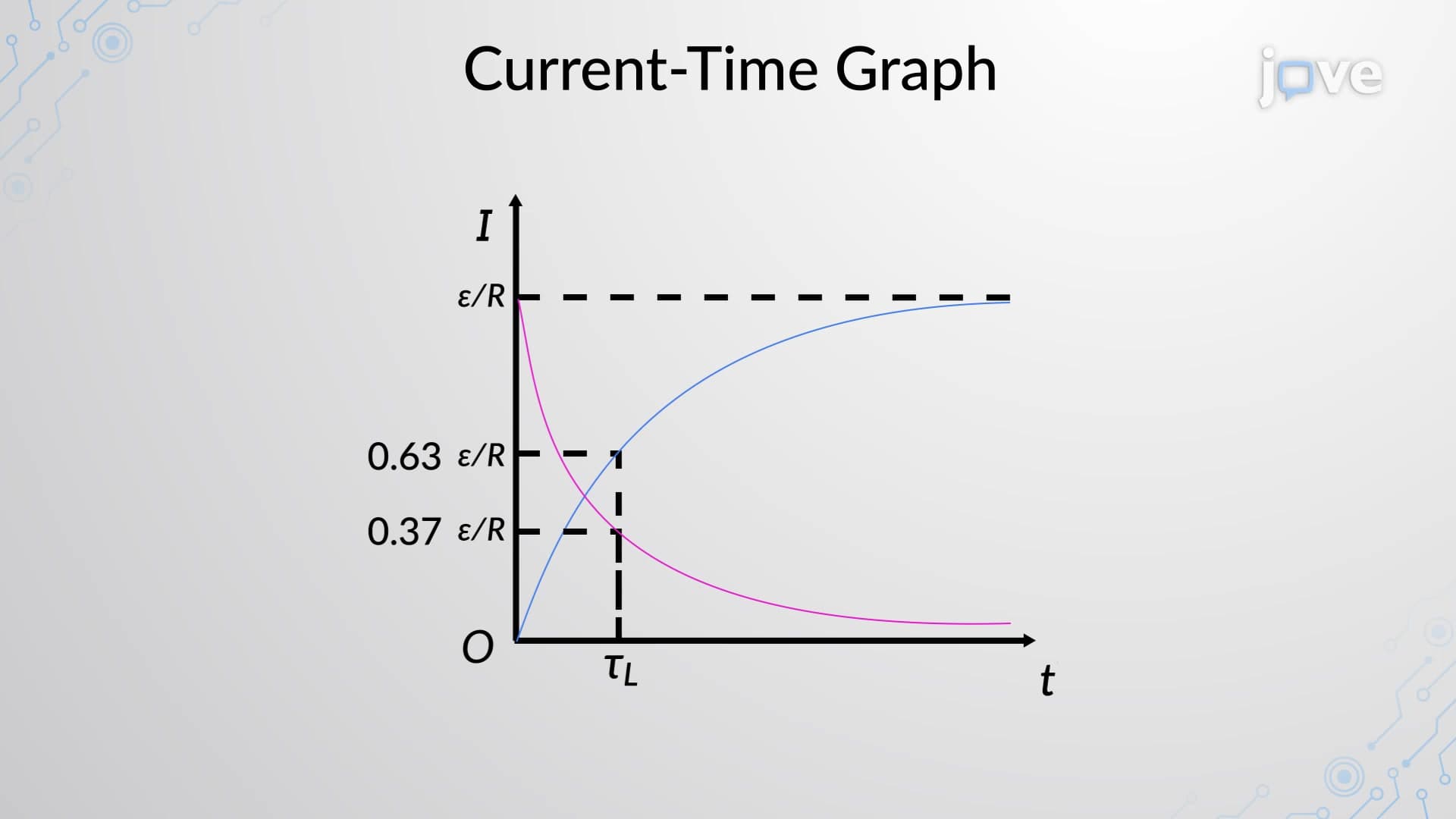
RL circuits exhibit opposite behavior due to Lenz's law governing electromagnetic induction. The inductor generates a back-EMF that opposes current changes, starting from zero current and gradually increasing to steady state. This principle underlies fluorescent light ballasts and automotive ignition systems used throughout the United States.
The energy storage comparison reveals why these circuits serve different functions. RC circuits store energy as electric potential between capacitor plates, making them ideal for timing circuits, power supplies, and audio crossover networks in American-manufactured speakers. The energy formula E = (1/2)CV² demonstrates how voltage and capacitance determine storage capacity.
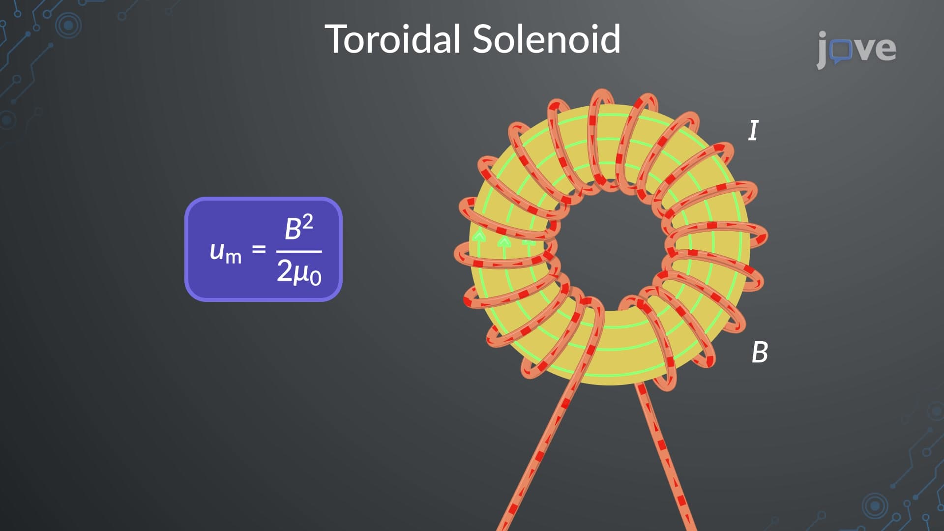
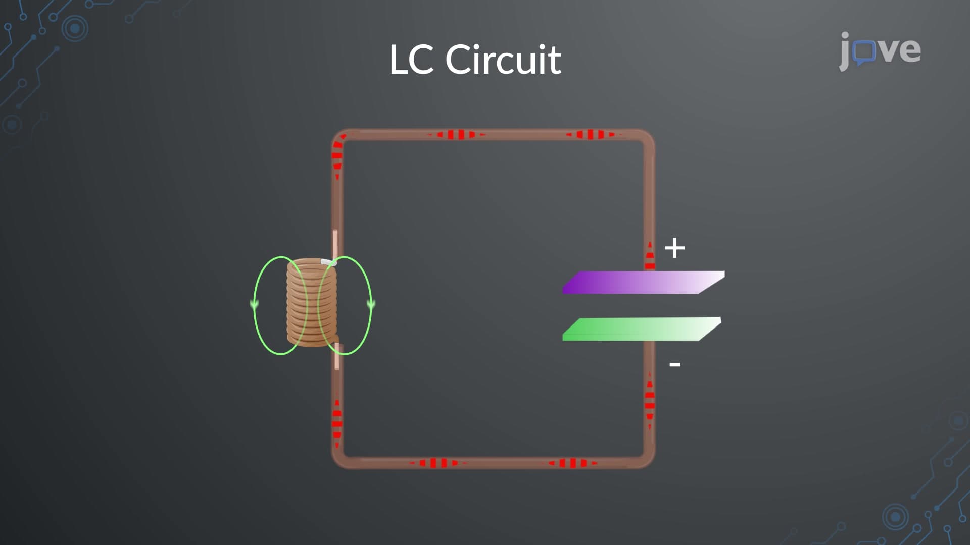
RL circuits store energy in magnetic fields surrounding inductors, calculated as E = (1/2)LI². This magnetic energy storage proves essential in power grid transformers, motor control systems, and the inductive charging stations emerging across US highways for electric vehicles.
When power sources disconnect, both circuits exhibit exponential decay but with different current behaviors. RC circuits show increasing current during capacitor discharge, while RL circuits demonstrate decreasing current as magnetic field energy dissipates. These decay patterns determine component selection in applications ranging from automotive electronics to medical devices used in American hospitals.
Understanding these time constants (τ = RC for capacitors, τ = L/R for inductors) helps engineers design circuits for specific timing requirements, whether for cardiac pacemaker timing or industrial automation systems. AP Physics students frequently encounter these concepts in both theoretical problems and laboratory experiments.
Related Micro-courses