Loading video…


 13 Concepts
 38.6K views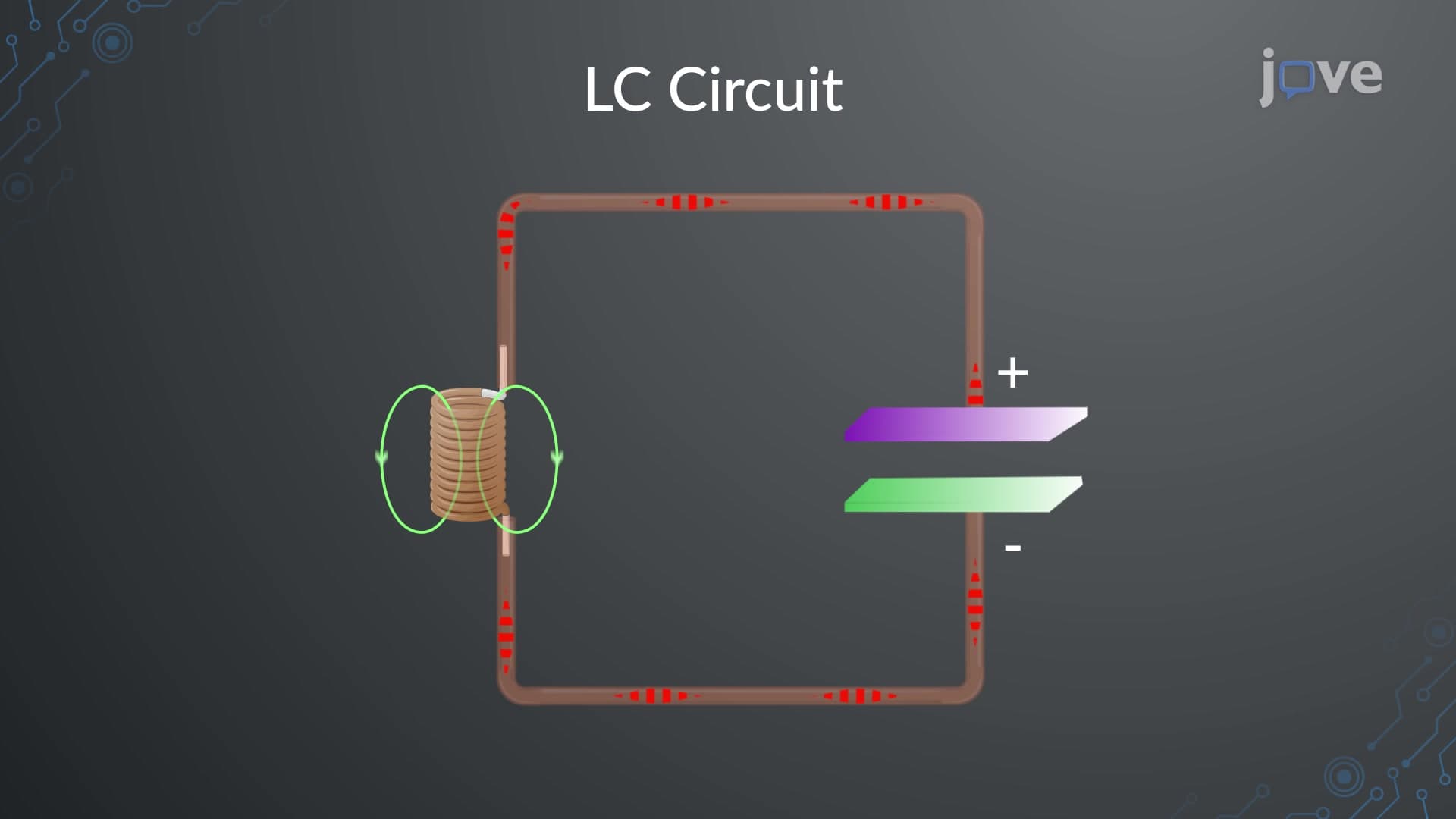

Video Summary: What are Lc Circuits
Ever wonder how your car's radio automatically tunes to different stations? LC circuits make this possible by creating precise electrical oscillations at specific frequencies. These fundamental electronic components combine inductors and capacitors to store and exchange energy, much like a pendulum swings back and forth. Tesla's wireless power transmission experiments famously utilized LC circuits to achieve resonant energy transfer. Watch the full video on JoVE Coach to master this concept with expert-led visuals and step-by-step explanations.
What are LC circuits? At their core, LC circuits represent one of the most elegant examples of energy exchange in electrical systems. These circuits consist of just two components: an inductor (L) that stores magnetic energy and a capacitor (C) that stores electrical energy. When connected together, they create a system that naturally oscillates between these two energy states, similar to how a pendulum exchanges potential and kinetic energy.
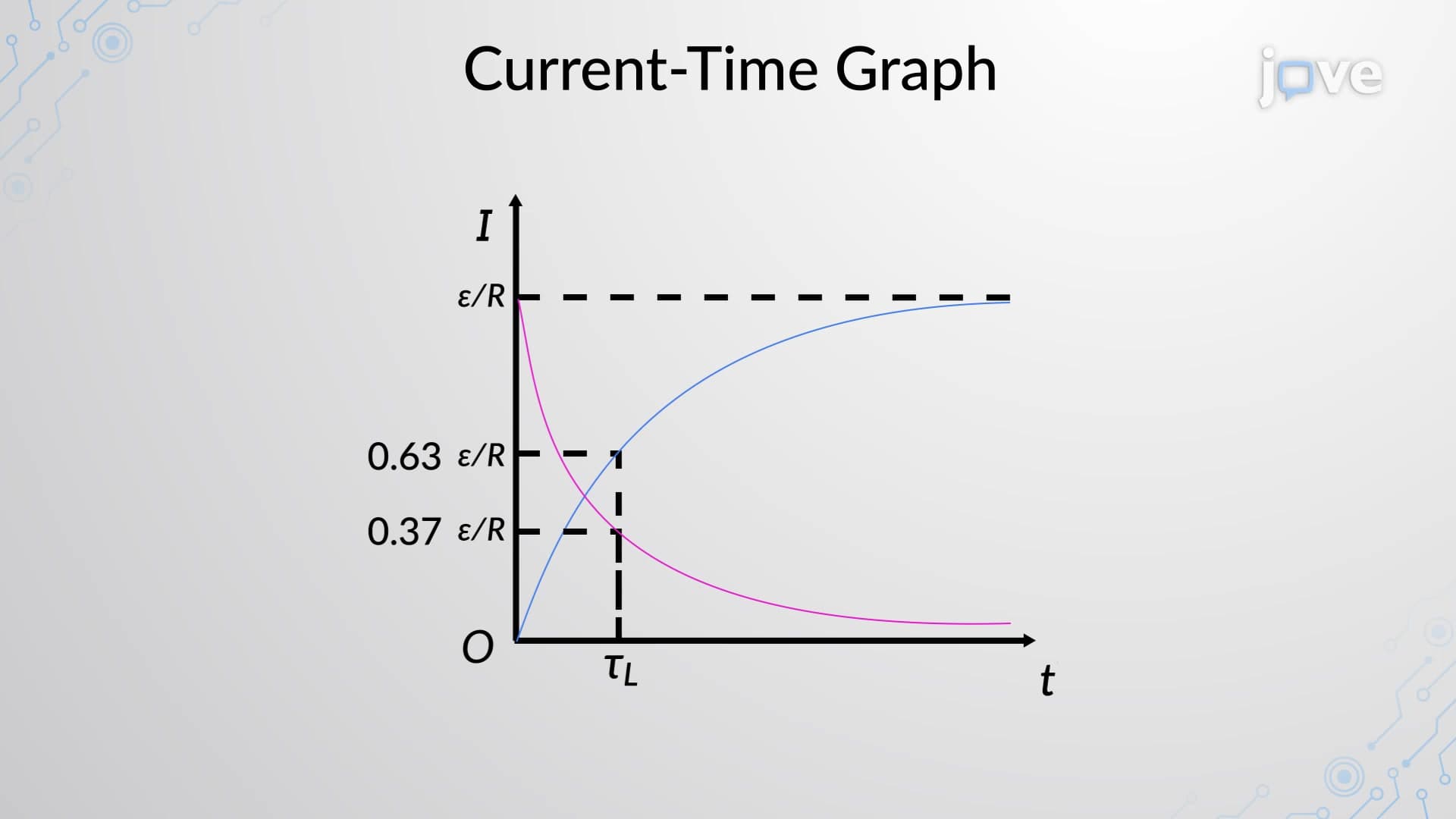
The beauty of LC circuits lies in their simplicity and predictable behavior. Unlike RC or RL circuits that eventually decay to steady states, ideal LC circuits continue oscillating indefinitely, making them perfect for understanding fundamental concepts in both electrical engineering and physics coursework.
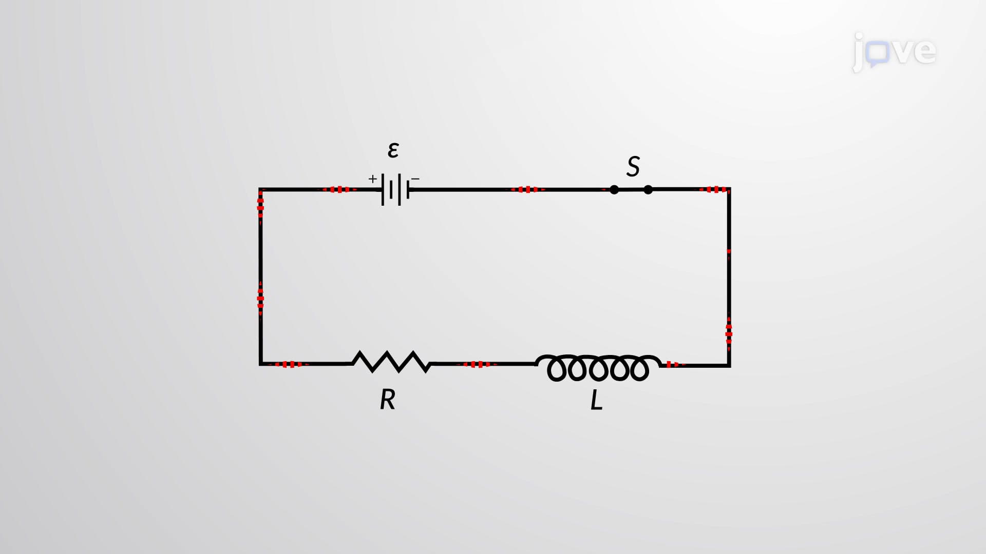
Different types of LC circuits serve various purposes in electronic applications. The most basic configuration is the series LC circuit, where the inductor and capacitor connect end-to-end in a single loop. This arrangement is commonly found in radio tuning circuits, where specific frequencies need to be selected or rejected.
Parallel LC circuits, known as tank circuits, connect the inductor and capacitor across the same two points. These circuits are frequently used in oscillators and frequency-selective applications. For students preparing for AP Physics C or college-level electrical engineering courses, understanding both configurations is crucial since exam problems often require analyzing different LC arrangements.
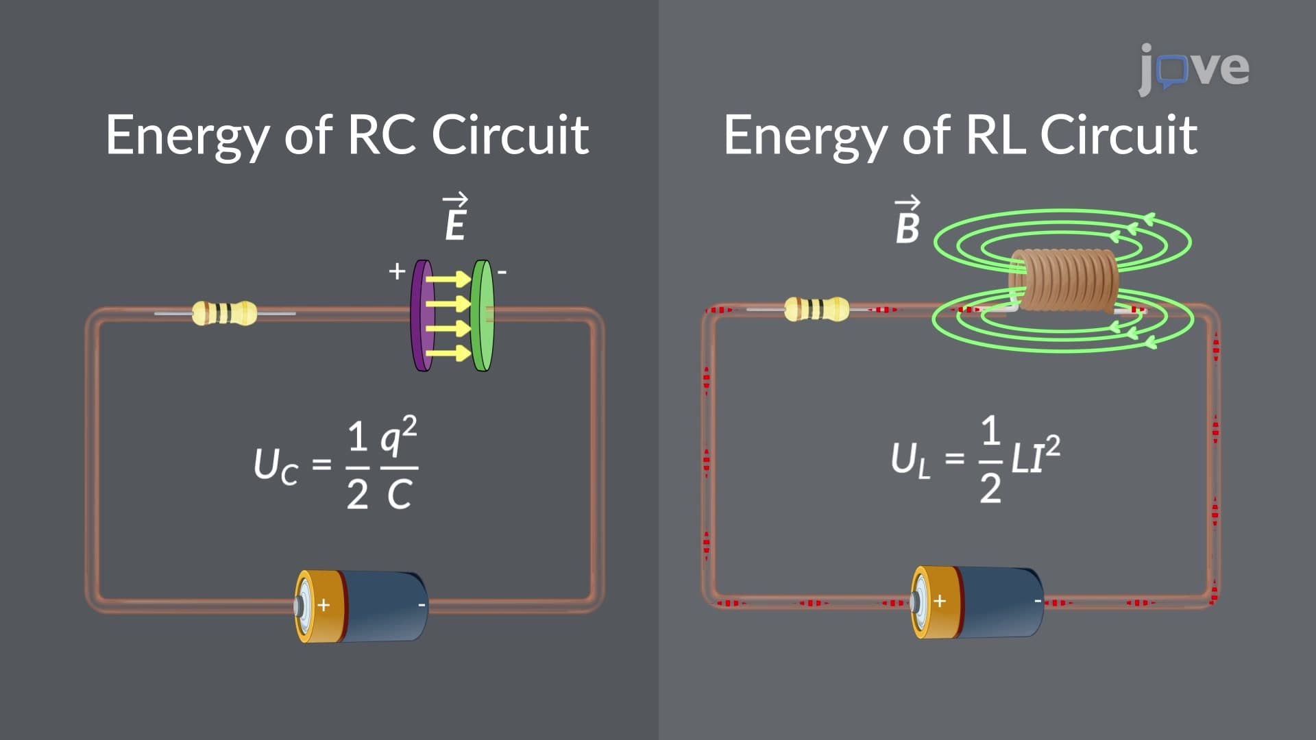
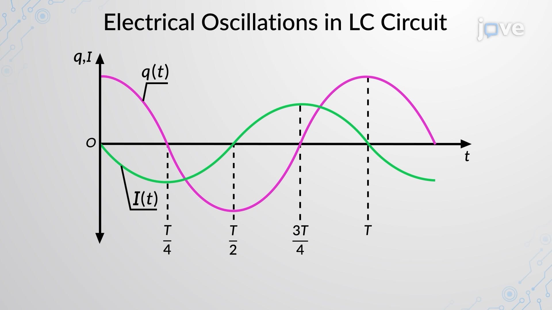
The fundamental principle governing LC circuit behavior centers on energy conservation. When a charged capacitor connects to an inductor, the stored electrical energy (E = (1/2)CV²) begins converting to magnetic energy (E = (1/2)LI²) as current flows. This process reverses continuously, creating sinusoidal voltage and current waveforms.
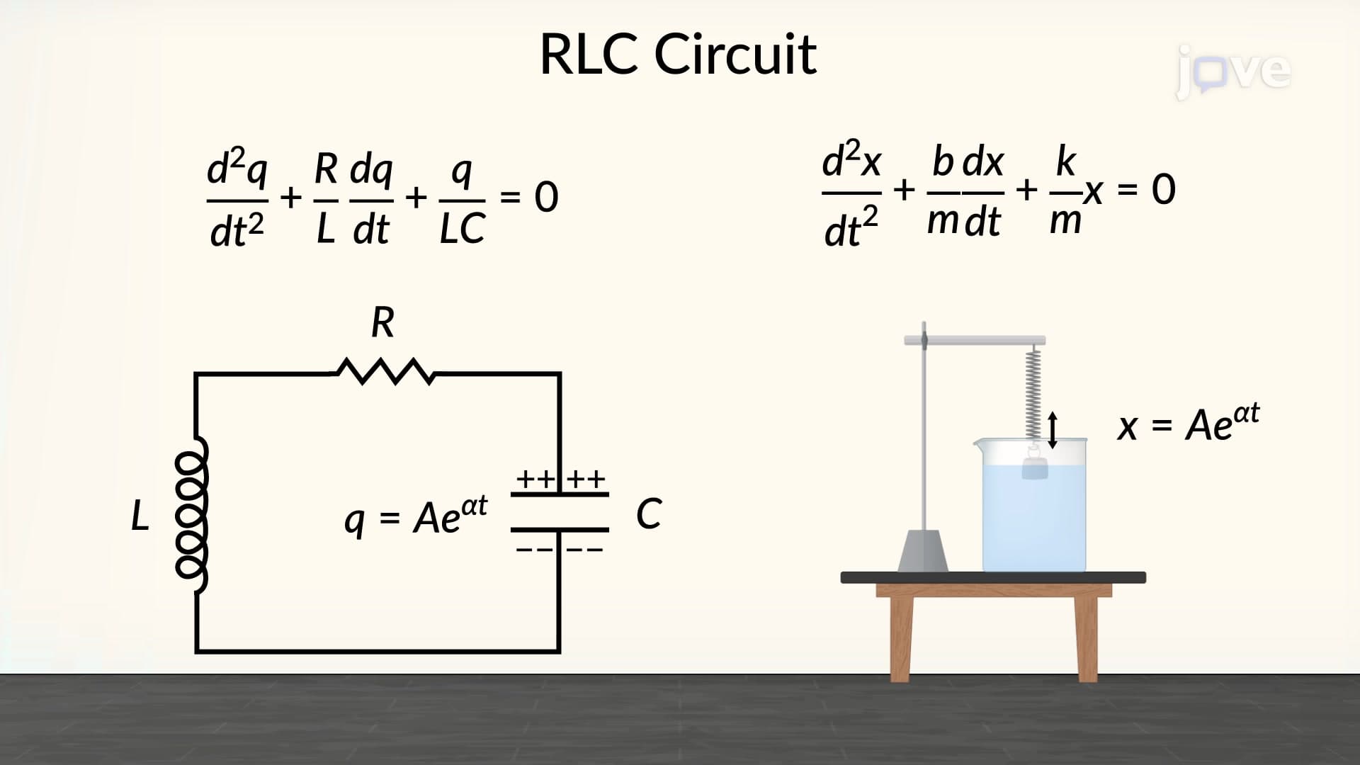
Students often struggle with this concept initially, but thinking of it like a mechanical spring-mass system helps. Just as a compressed spring converts potential energy to kinetic energy and back again, LC circuits exchange electrical and magnetic energy. This analogy frequently appears on MCAT physics sections and college physics exams.
The governing equation for LC circuits, L(d²q/dt²) + q/C = 0, mirrors the simple harmonic oscillator equation. This relationship yields the natural frequency f = 1/(2π√(LC)), which determines how fast the circuit oscillates. Understanding this frequency relationship is essential for analyzing resonance phenomena in more complex circuits.
In practical applications, AM radio receivers use LC circuits tuned to specific frequencies, allowing you to select different stations. Variable capacitors in these radios change the resonant frequency, effectively "tuning" the circuit. Engineering students will encounter these principles in courses like Circuit Analysis and Electromagnetic Theory, where LC circuit behavior forms the foundation for more advanced topics like filters and amplifiers.
Related Micro-courses