Loading video…


 13 Concepts
 38.6K views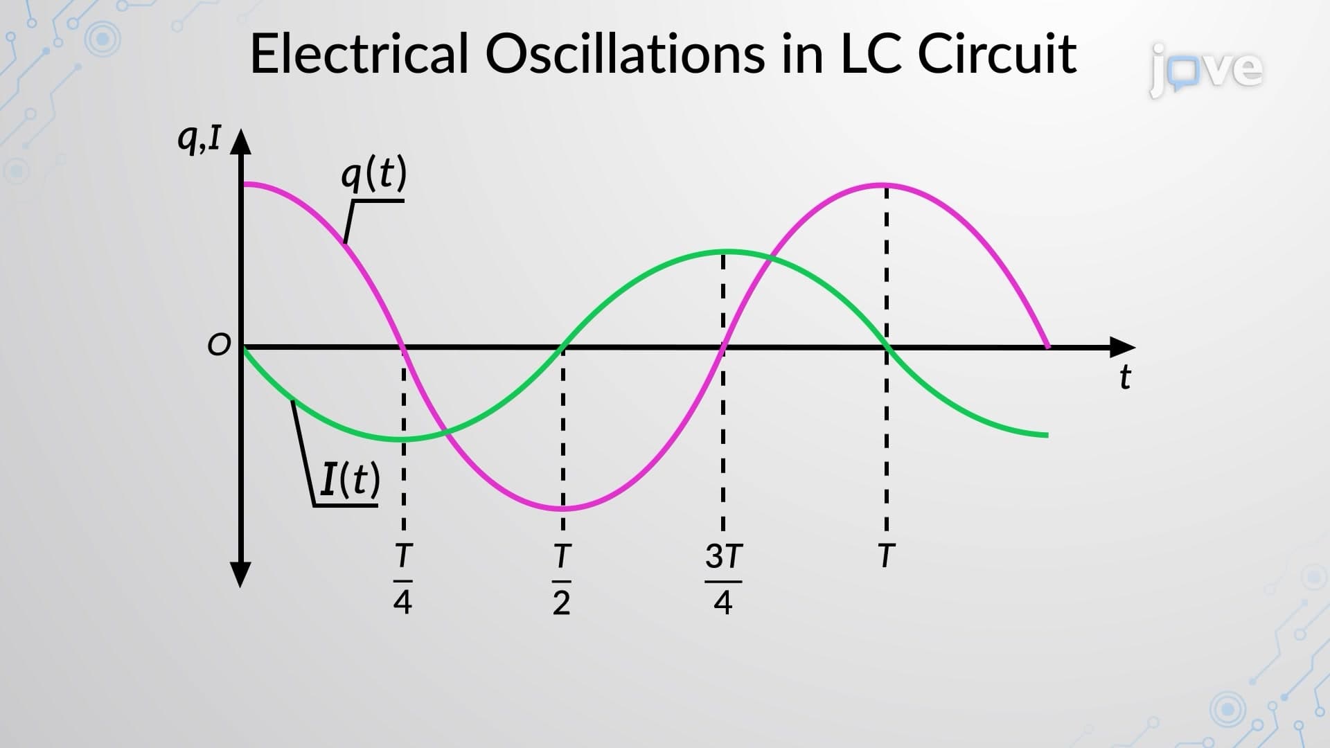

Video Summary: Oscillations in an Lc Circuit Explained
Ever wonder how your smartphone's wireless charging works? The answer lies in oscillations in an LC circuit, where electrical energy seamlessly transforms between electric and magnetic fields. From the Tesla coils at Boston's Museum of Science to the radio transmitters broadcasting from New York's Empire State Building, LC circuits create the rhythmic energy exchanges that power modern electronics. Oscillations in An LC Circuit Explained reveals how capacitors and inductors work together to create these perpetual energy cycles. Watch the full video on JoVE Coach to master this concept with expert-led visuals and step-by-step explanations.
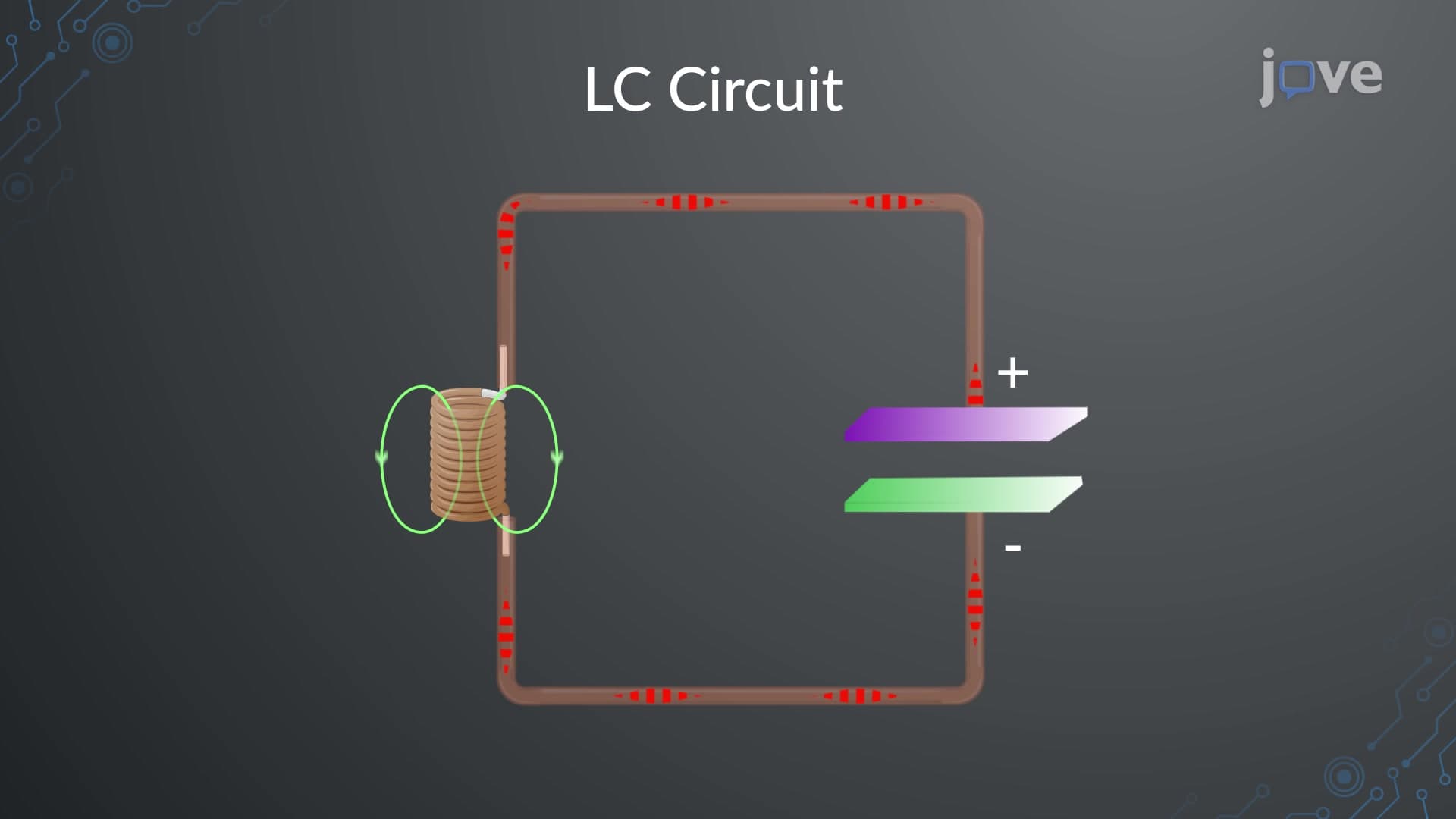
Oscillations in an LC circuit represent one of the most elegant demonstrations of energy conservation in electrical systems. When a charged capacitor connects to an inductor, the circuit creates a closed loop where electrical energy continuously transforms between two forms: the electric field energy stored in the capacitor and the magnetic field energy stored in the inductor. This transformation occurs without energy loss in an ideal circuit, creating perpetual oscillations that follow predictable mathematical patterns.
The oscillatory behavior emerges from the fundamental properties of both components. Capacitors resist changes in voltage, while inductors resist changes in current. This opposition creates a natural "push-pull" effect that sustains the energy exchange cycle indefinitely.
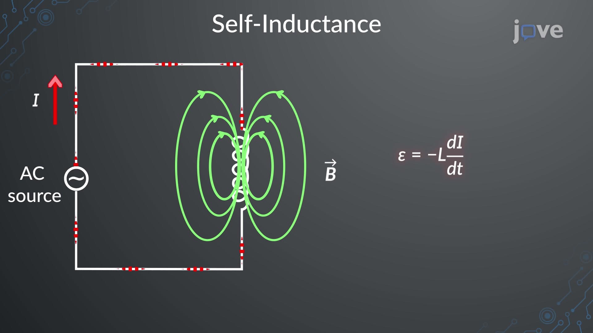
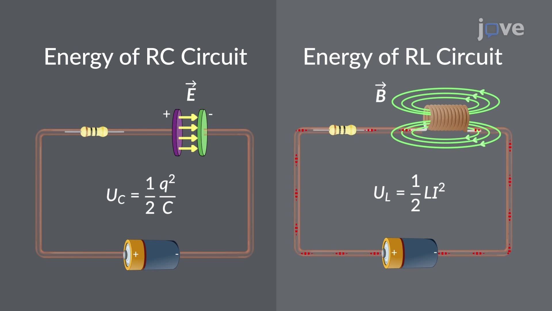
The energy transfer process follows a precise sequence that repeats continuously. Initially, when the capacitor holds maximum charge, all circuit energy exists as electric field energy (E = Q²/2C). At this moment, current flow equals zero. As the capacitor discharges through the inductor, electric field energy decreases while magnetic field energy increases. The inductor's self-inductance property prevents instantaneous current changes, causing current to build gradually.
When the capacitor fully discharges, all energy has transferred to the inductor's magnetic field (E = LI²/2), and current reaches its maximum value. The inductor then "fights" to maintain this current flow, pushing charge back onto the capacitor plates with opposite polarity. This reverse charging process converts magnetic energy back to electric energy, completing one half-cycle of oscillation.
LC circuit oscillations follow sinusoidal patterns described by the angular frequency ω = 1/√(LC). This relationship appears frequently on AP Physics exams and college-level electrical engineering coursework. The charge on the capacitor varies as Q(t) = Q₀cos(ωt), while current follows I(t) = -Q₀ω sin(ωt), demonstrating a 90-degree phase difference between these quantities.
These principles find extensive application in modern technology. Radio stations use LC circuits tuned to specific frequencies for signal transmission. The 88-108 MHz FM radio band relies on LC oscillators in both transmitters and receivers. Medical devices like MRI machines employ LC circuits in their radiofrequency systems. Even smartphone wireless charging pads use LC circuits operating at 6.78 MHz to transfer power efficiently.
Understanding LC oscillations proves essential for students pursuing STEM careers. Electrical engineering programs at institutions like MIT and Stanford emphasize these concepts in introductory circuits courses. The MCAT physics section frequently tests oscillation concepts, particularly energy conservation principles. Students preparing for AP Physics C: Electricity and Magnetism encounter LC circuits in both multiple-choice and free-response questions.
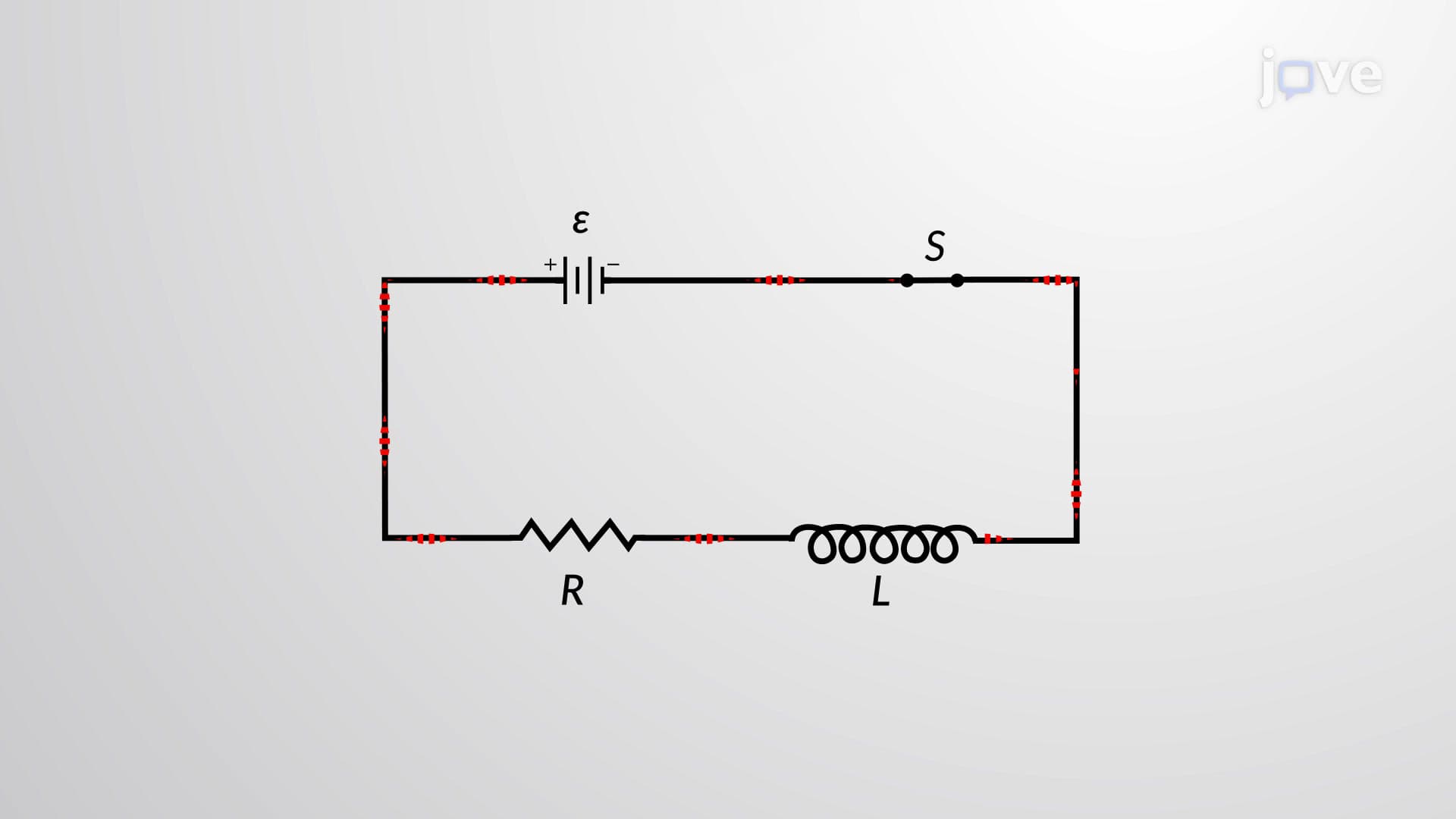
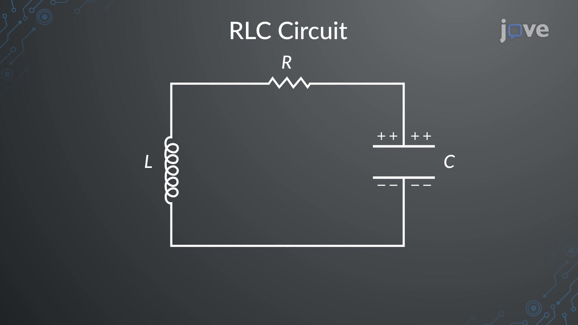
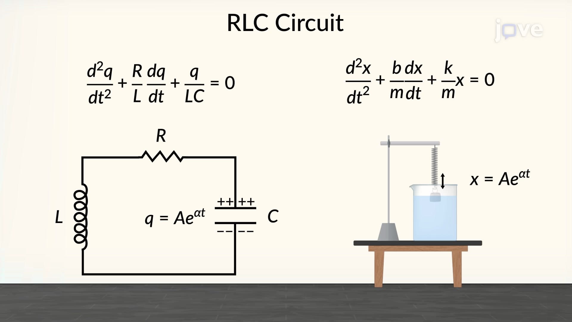
Perfect LC oscillations require ideal components with no resistance. Real circuits always contain some resistance, causing oscillation amplitude to decay exponentially. This damping effect leads to more complex RLC circuit analysis, forming the foundation for advanced topics in signal processing and control systems.
Related Micro-courses