14 Concepts
15 Concepts
14 Concepts
11 Concepts
16 Concepts
10 Concepts
15 Concepts
12 Concepts
19 Concepts
14 Concepts
14 Concepts
12 Concepts
24 Concepts
22 Concepts
15 Concepts
15 Concepts
17 Concepts
15 Concepts
13 Concepts
19 Concepts
12 Concepts
16 Concepts
13 Concepts
15 Concepts
12 Concepts
13 Concepts
18 Concepts
12 Concepts
22 Concepts
21 Concepts
13 Concepts
13 Concepts
14 Concepts
Inductance is a fundamental electromagnetic property that describes how conductors generate magnetic fields when current flows through them and resist changes in current flow. This comprehensive course explores self-inductance in single conductors, mutual inductance between coupled coils (like in power transformers used throughout US electrical grids), and the behavior of RL, LC, and RLC circuits found in everything from radio tuners to switching power supplies. Master these concepts with JoVE Coach to excel in physics coursework and standardized exams.
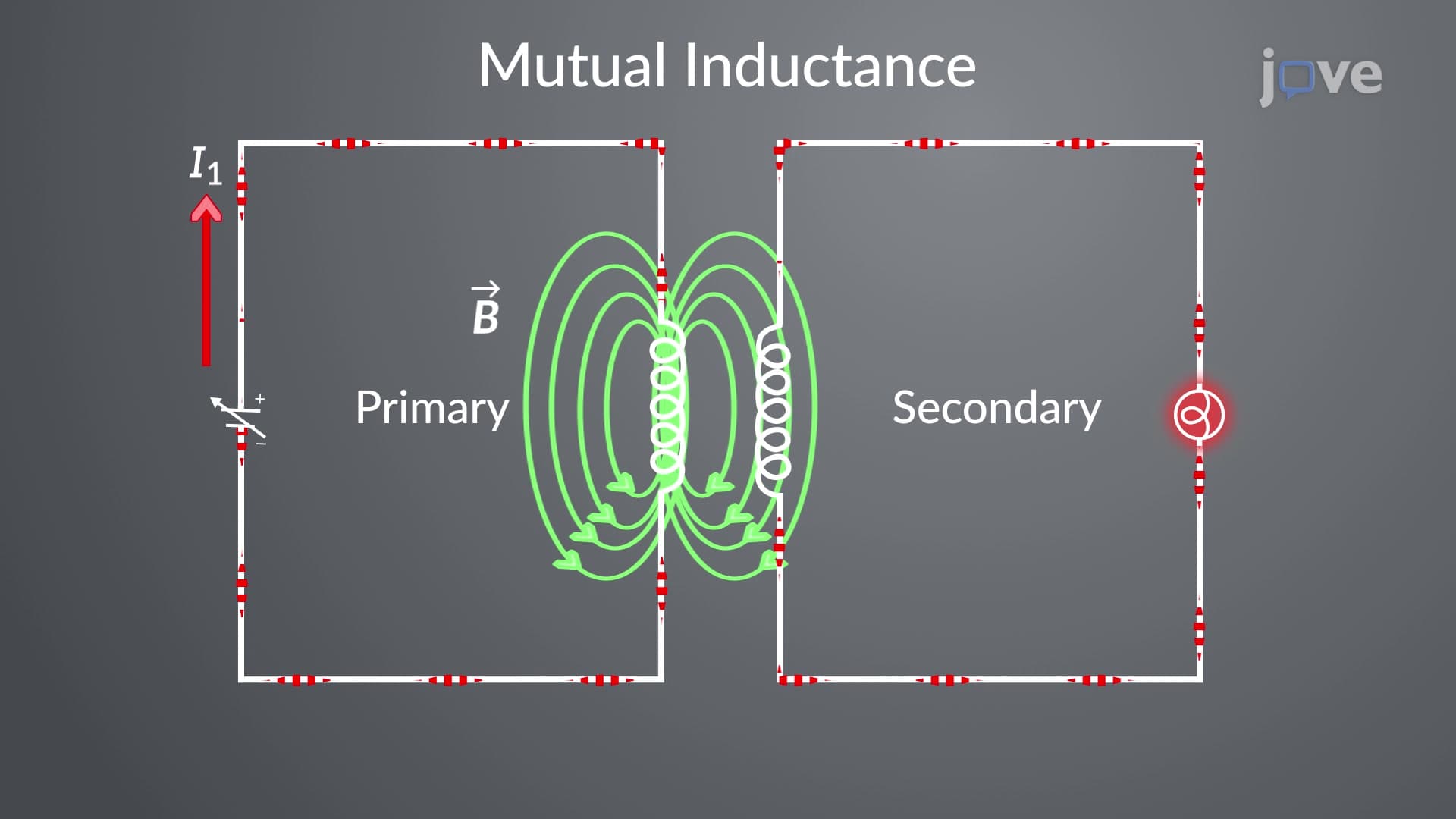
1. Mutual Inductance and Transformer Principles: Mutual inductance occurs when changing current in one coil induces voltage in a nearby coil, forming the basis for power transformers used throughout US electrical infrastructure. The mutual inductance coefficient M depends only on coil geometry and orientation, measured in henries. This principle enables voltage conversion in everything from household electronics to power grid substations. When primary coil current I₁ changes, it creates magnetic flux through the secondary coil, inducing EMF = -M(dI₁/dt). Understanding mutual inductance explains how cell phone chargers step down 120V household current and how utility transformers distribute electricity across American cities.
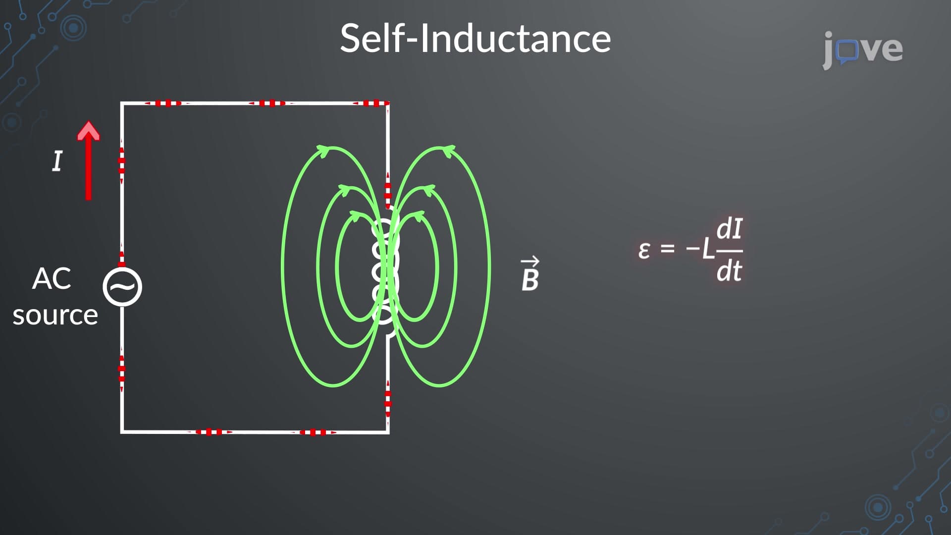
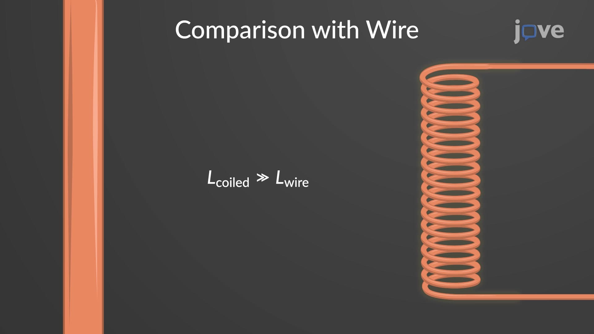
2. Self-Inductance in Circuit Elements: Self-inductance represents a conductor's opposition to current changes, generating back-EMF according to Lenz's law. Every current-carrying conductor exhibits self-inductance, but coiled configurations like solenoids dramatically increase this property by a factor of N² compared to straight wires. For a solenoid with N turns, length l, and area A: L = μ₀N²A/l. This explains why inductors use coiled wire rather than straight conductors. Self-inductance appears in fluorescent light ballasts, preventing rapid current changes that could damage components, and in car ignition systems where rapid current interruption creates high-voltage sparks.
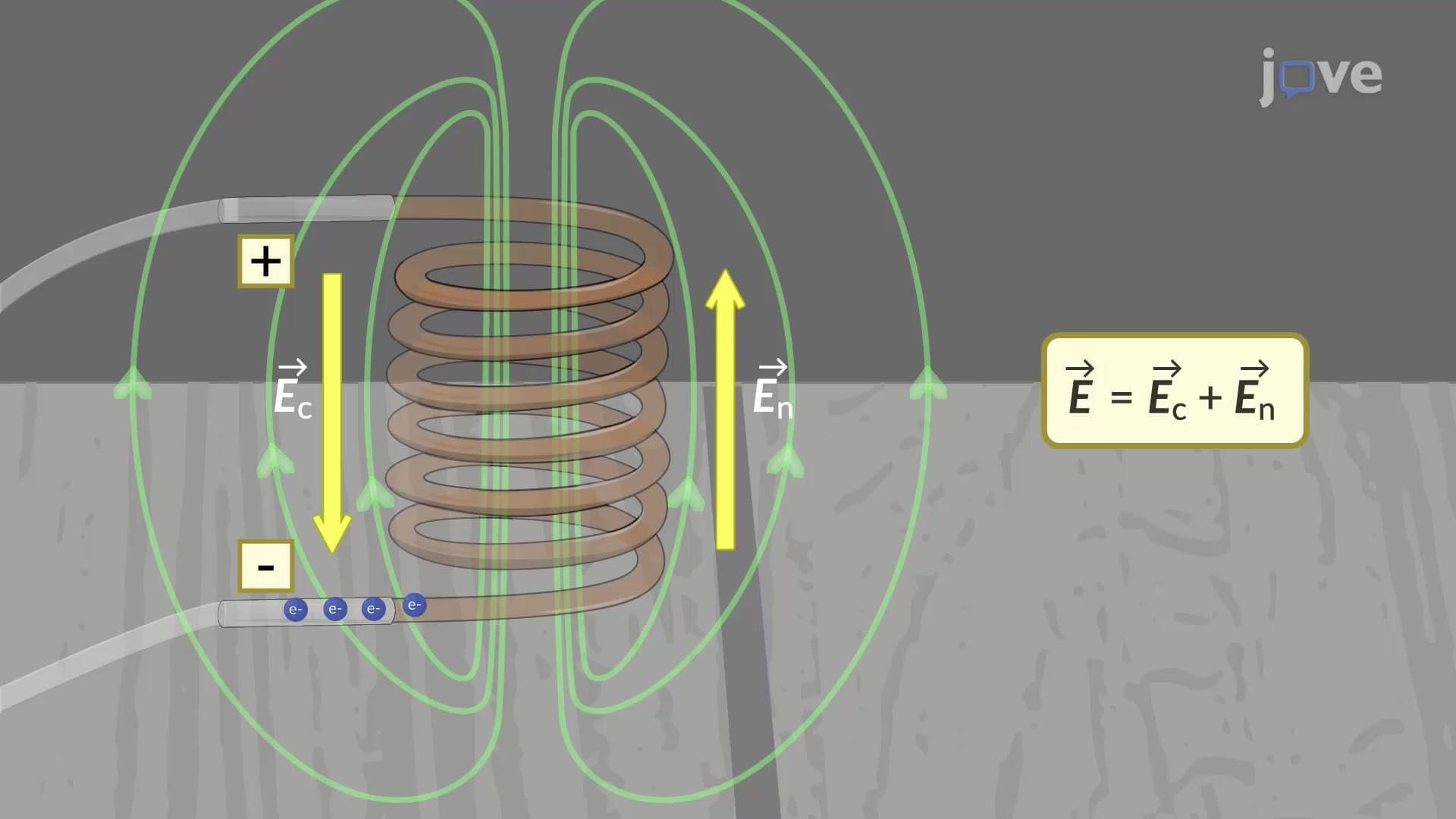
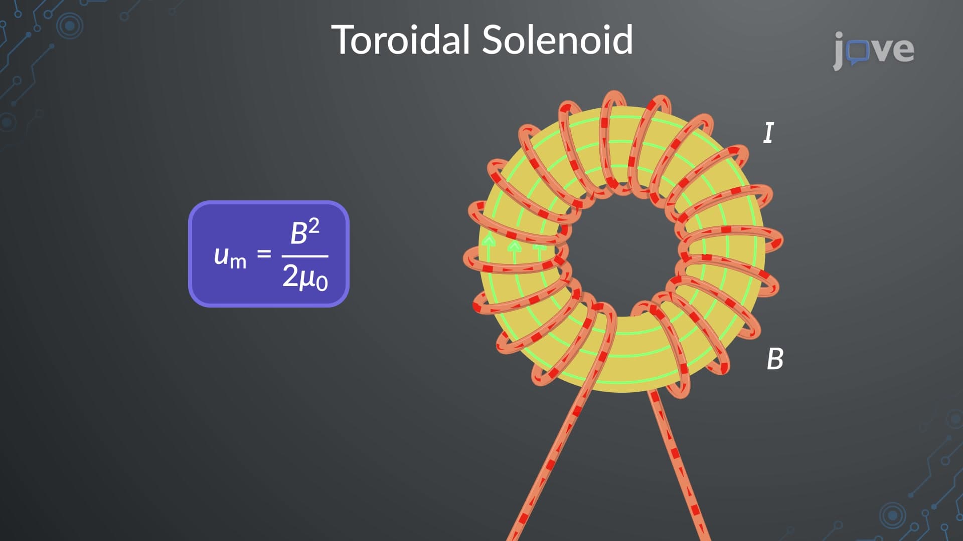
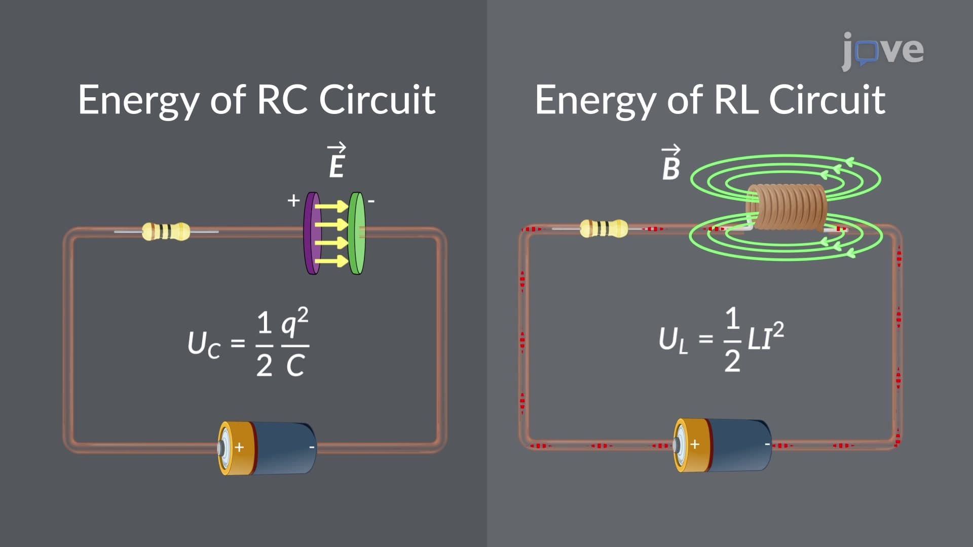
3. Inductor Behavior and Circuit Analysis: Inductors store energy in magnetic fields and resist current changes by generating opposing voltage V = -L(di/dt). Unlike resistors that dissipate energy as heat, ideal inductors temporarily store energy as UB = ½LI². This energy storage principle operates in switching power supplies found in laptop computers and LED drivers. When current through an inductor changes, electrons accumulate on terminals to create electric fields that exactly cancel the magnetically-induced fields within the coil. This fundamental behavior explains why inductors act as "current sources" in DC circuits and create impedance in AC applications like audio crossover networks.
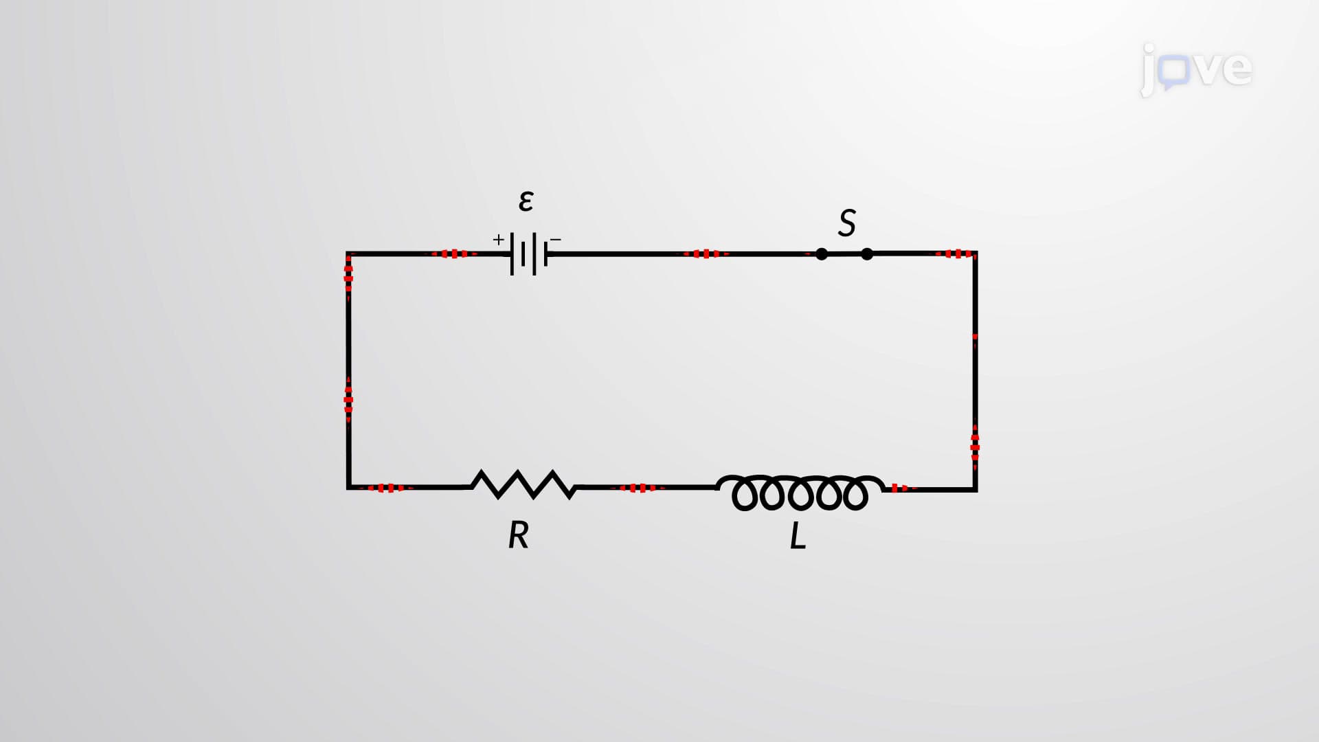
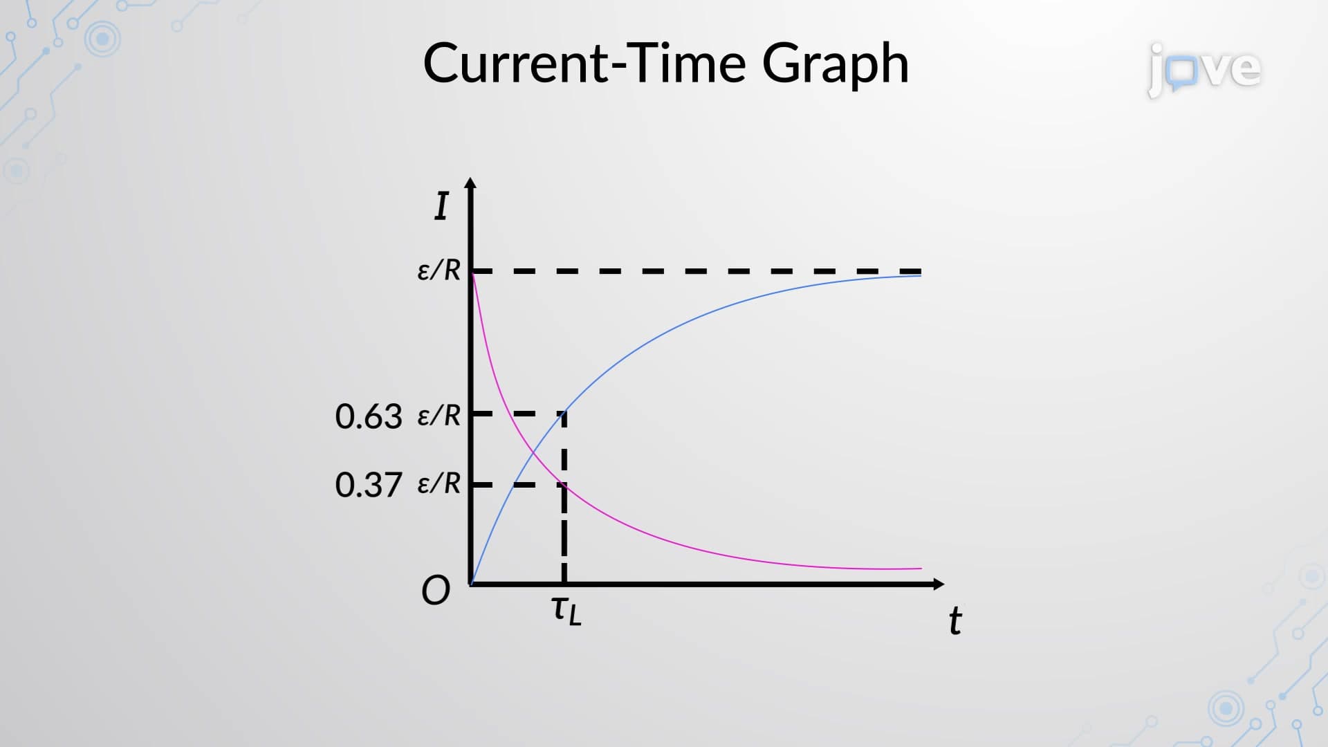
4. RL Circuit Dynamics and Time Constants: RL circuits exhibit exponential current growth when energized and exponential decay when de-energized, characterized by time constant τ = L/R. During growth, current approaches final value I∞ = V/R according to i(t) = (V/R)(1 - e^(-t/τ)). At t = τ, current reaches 63% of final value; during decay, current drops to 37% of initial value. This behavior appears in automotive ignition systems where rapid current interruption through inductive coils generates high voltages for spark plugs. Understanding RL dynamics helps explain why large motors require soft-start circuits and why fluorescent lights need time to reach full brightness.
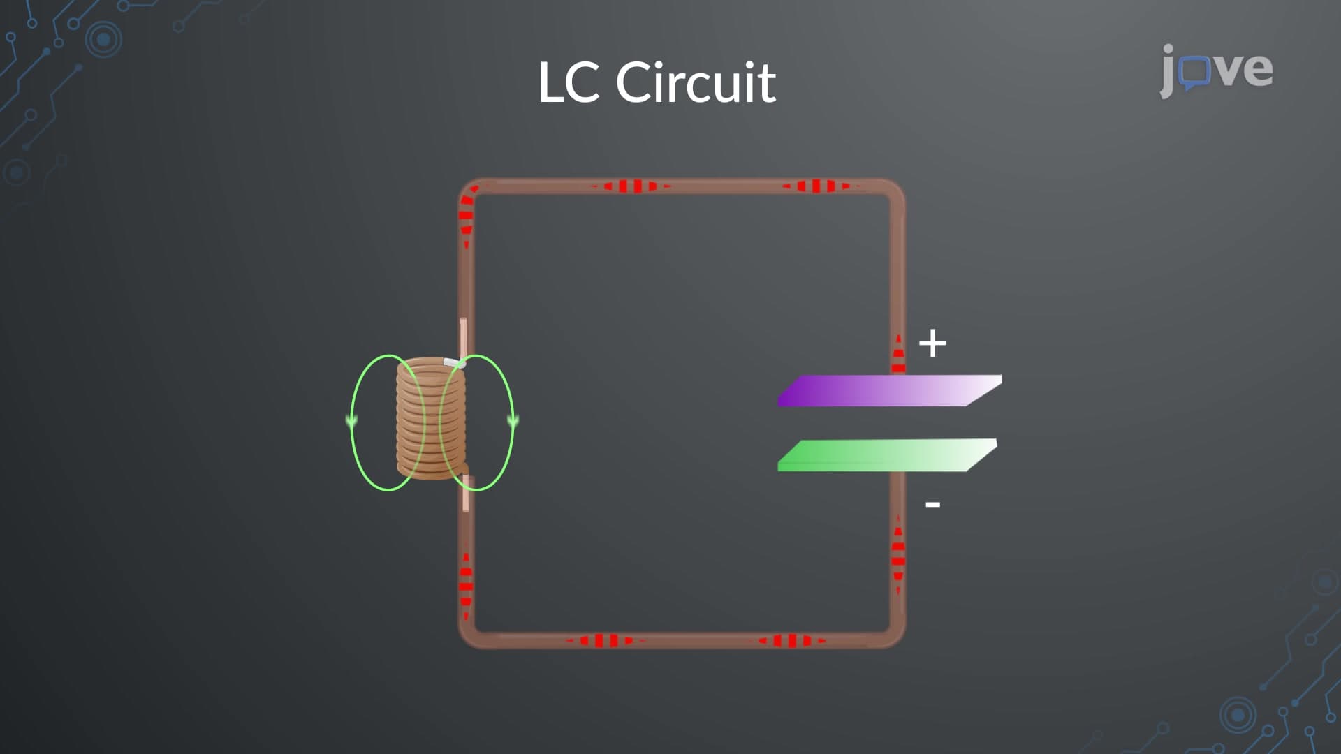
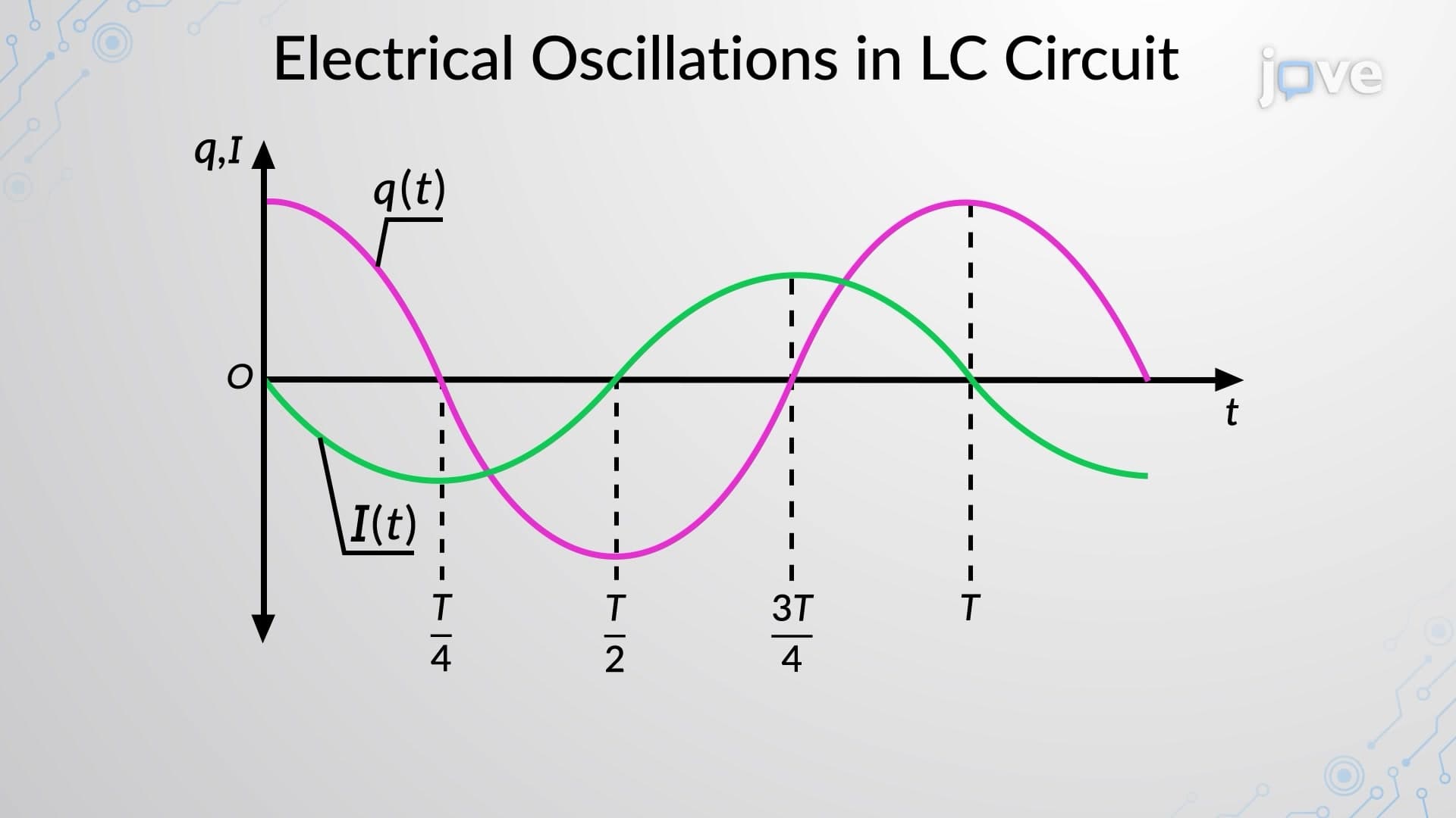
5. LC Oscillations and Resonance: LC circuits create electrical oscillations similar to mechanical pendulums, with energy alternating between electric fields (capacitor) and magnetic fields (inductor). The natural frequency f₀ = 1/(2π√LC) determines oscillation rate, forming the basis for radio tuning circuits. Initially charged capacitors discharge through inductors, building magnetic fields that maintain current flow even after capacitor discharge. This continued current recharges capacitors with opposite polarity, creating sinusoidal oscillations. AM/FM radio receivers use LC circuits tuned to specific frequencies, while quartz crystal oscillators in digital clocks exploit similar resonance principles for accurate timekeeping.
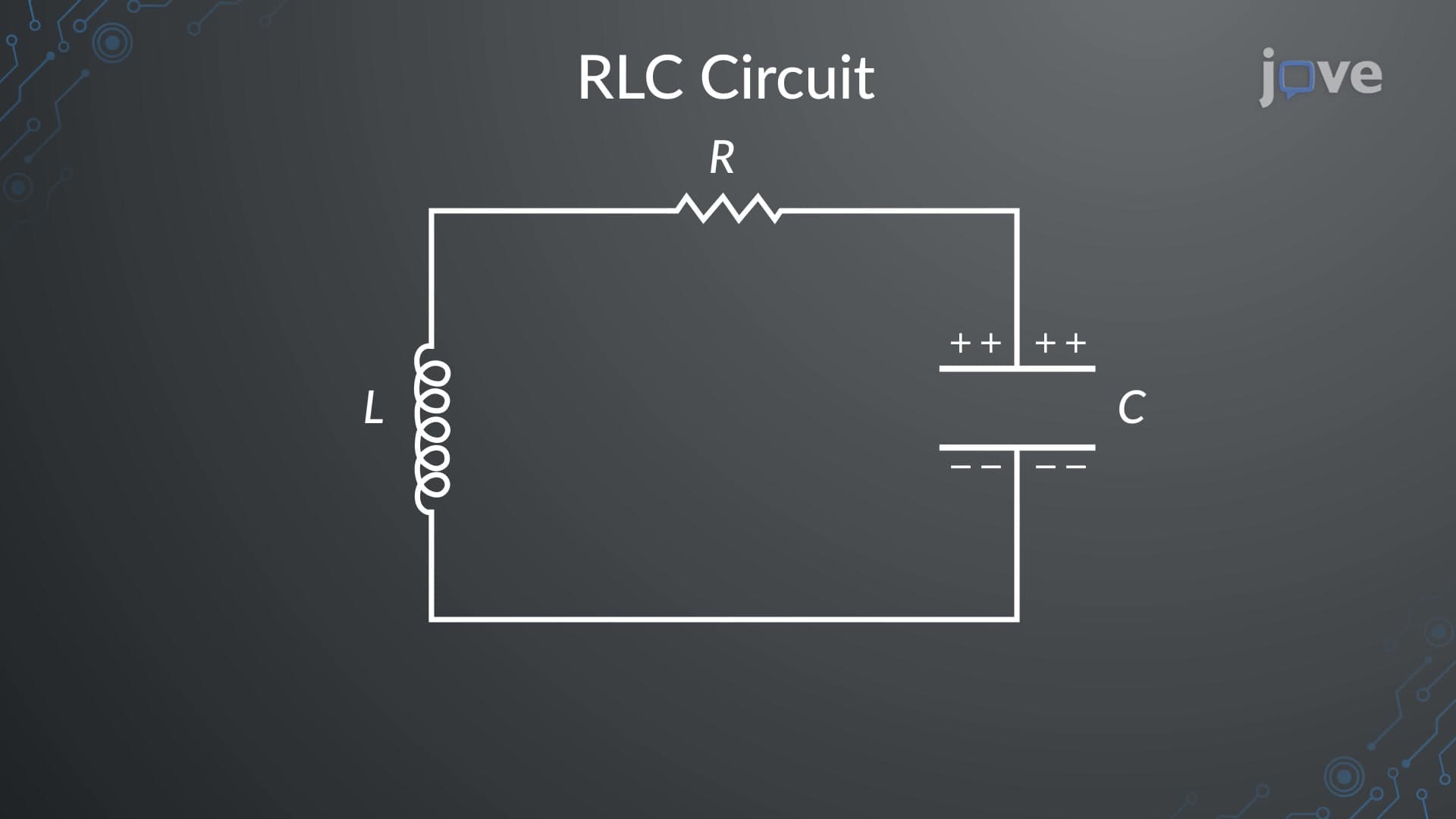
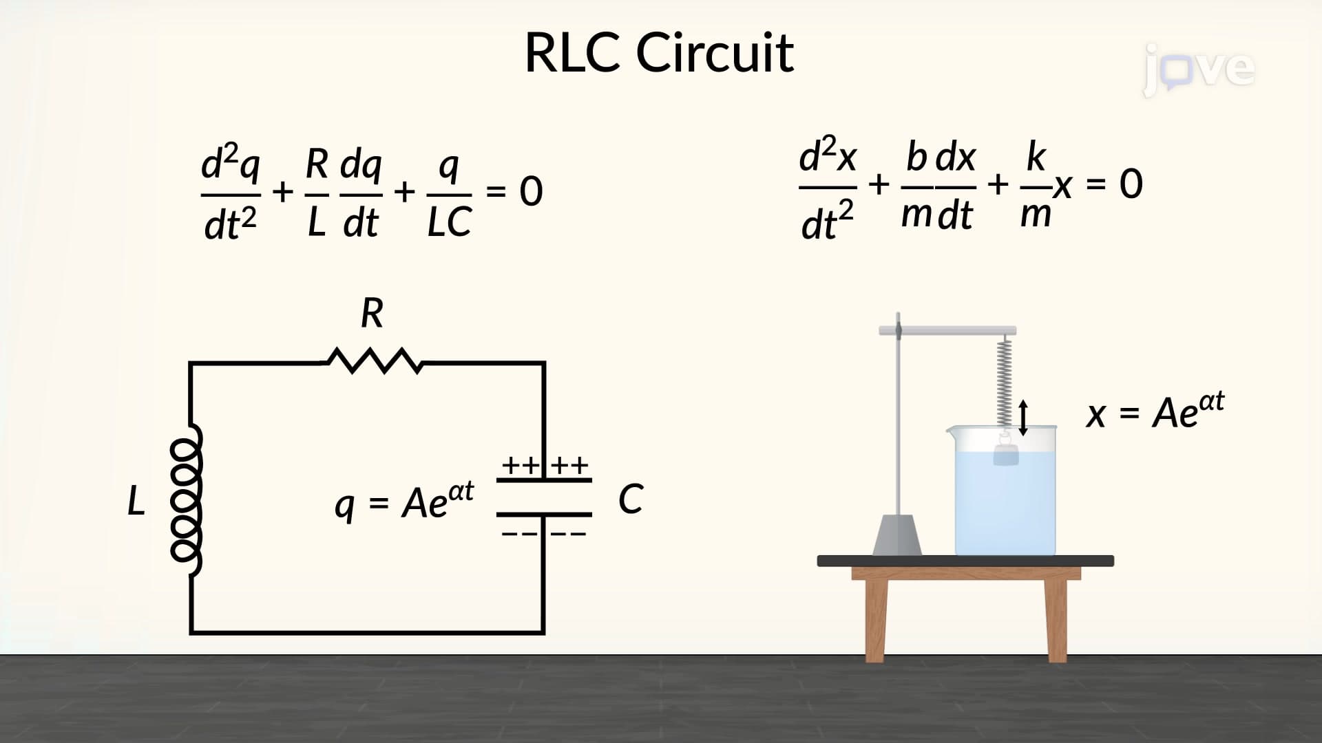
6. RLC Circuits and Damped Oscillations: Adding resistance to LC circuits creates damped oscillations where energy dissipates as heat, causing amplitude decay over time. Three distinct behaviors emerge: underdamped (oscillating with decreasing amplitude), critically damped (fastest approach to equilibrium without overshoot), and overdamped (slow exponential decay). These characteristics determine optimal designs for various applications - car suspension systems use critically damped shock absorbers for smooth rides, while audio speakers employ underdamped voice coil circuits for accurate sound reproduction. Understanding RLC behavior helps engineers design stable power supplies and prevents unwanted oscillations in electronic circuits.