14 Concepts
15 Concepts
14 Concepts
11 Concepts
16 Concepts
10 Concepts
15 Concepts
12 Concepts
19 Concepts
14 Concepts
14 Concepts
12 Concepts
24 Concepts
22 Concepts
15 Concepts
15 Concepts
17 Concepts
15 Concepts
13 Concepts
19 Concepts
12 Concepts
16 Concepts
13 Concepts
15 Concepts
12 Concepts
13 Concepts
18 Concepts
12 Concepts
22 Concepts
21 Concepts
13 Concepts
13 Concepts
14 Concepts
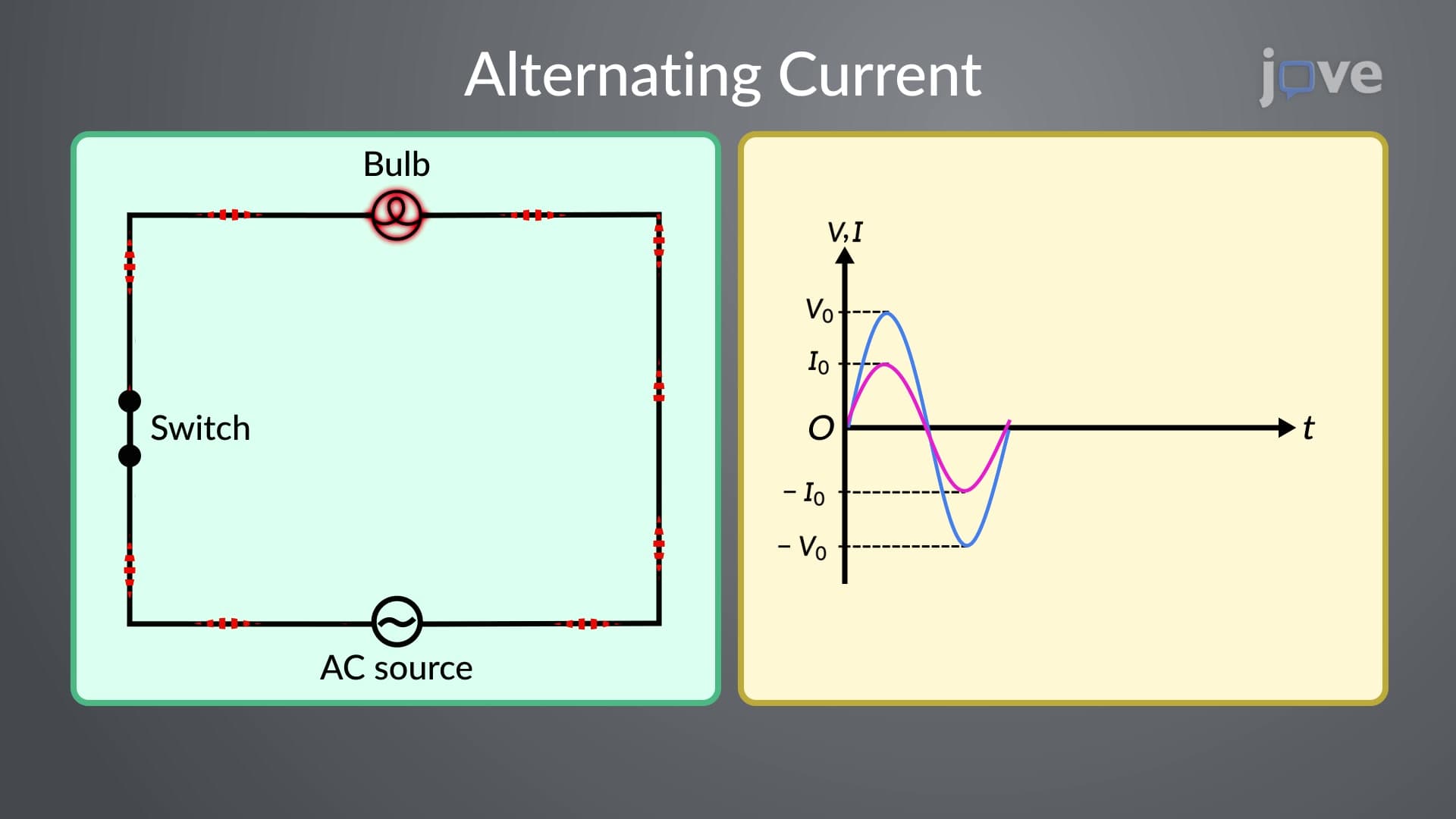
AC circuits form the foundation of modern electrical systems, powering everything from household appliances to industrial machinery across the United States. This comprehensive course explores the analysis of alternating-current circuits, covering impedance reactance relationships, RLC circuit behavior, resonance phenomena, and transformer operations. Master essential concepts including phasors, power factor calculations, and circuit analysis techniques with JoVE Coach's expert instruction.
1. AC Sources and Waveform Characteristics AC circuits utilize sources that produce sinusoidally varying voltages and currents, unlike the constant values in DC circuits. The key parameters include amplitude (peak value), frequency (cycles per second), and period (time for one complete cycle). In the United States, standard household AC operates at 60 Hz frequency with 120V RMS voltage. Understanding these waveform characteristics is essential for analyzing any AC system, from simple household circuits to complex industrial power networks.
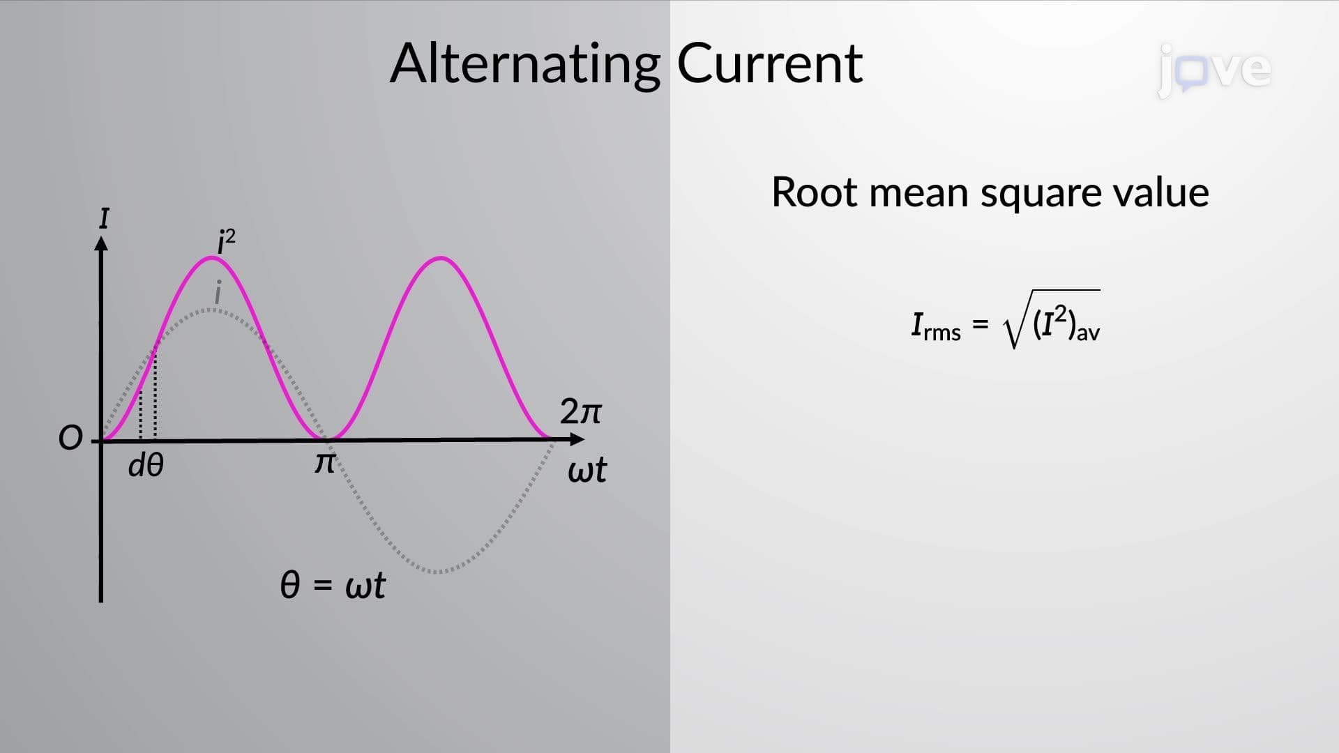
2. RMS Values and Average Calculations Root-mean-square (RMS) values represent the effective value of AC quantities, providing a meaningful way to compare AC and DC power delivery. The RMS value equals the DC value that would produce the same heating effect in a resistor. For sinusoidal waveforms, RMS values are 0.707 times the peak values. This concept is crucial because all AC voltage and current ratings on US electrical equipment refer to RMS values, making it essential for practical circuit analysis.
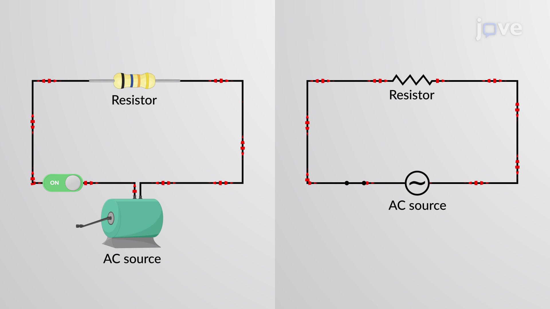
3. Resistive AC Circuits and Phase Relationships In purely resistive AC circuits, voltage and current remain in phase, meaning they reach their maximum and minimum values simultaneously. This relationship simplifies analysis since Ohm's law applies directly using RMS values. Common examples include incandescent light bulbs and electric heaters found in American homes. Understanding this phase relationship provides the foundation for analyzing more complex circuits containing reactive components.
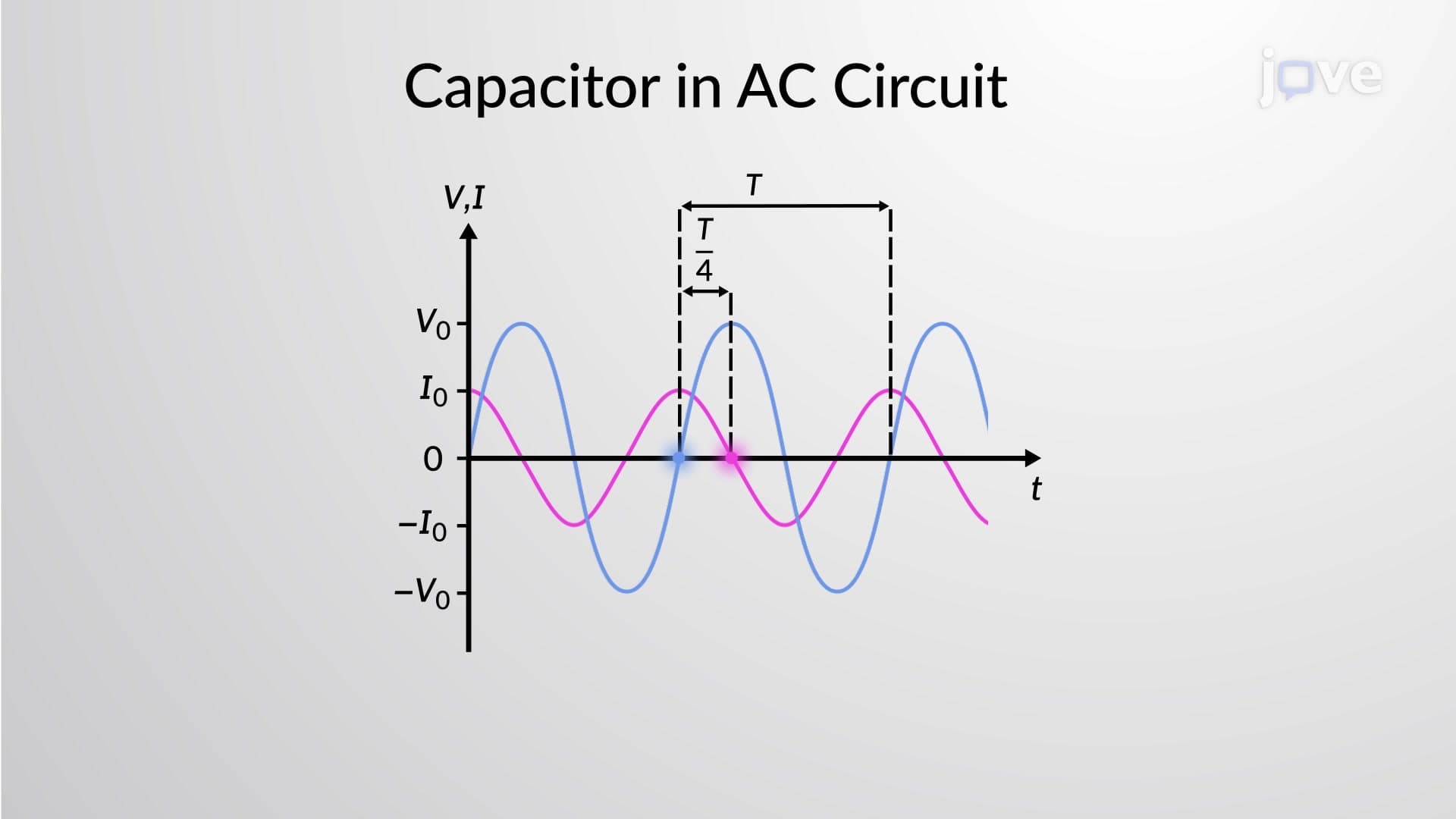
4. Capacitive Reactance and Leading Current Capacitors in AC circuits exhibit reactance that opposes current flow, with the unique characteristic that current leads voltage by 90 degrees. Capacitive reactance decreases with increasing frequency, making capacitors useful for filtering applications in electronic devices. In US power systems, capacitors are often used for power factor correction in industrial facilities. The reactance formula XC = 1/(2πfC) shows this inverse frequency relationship clearly.
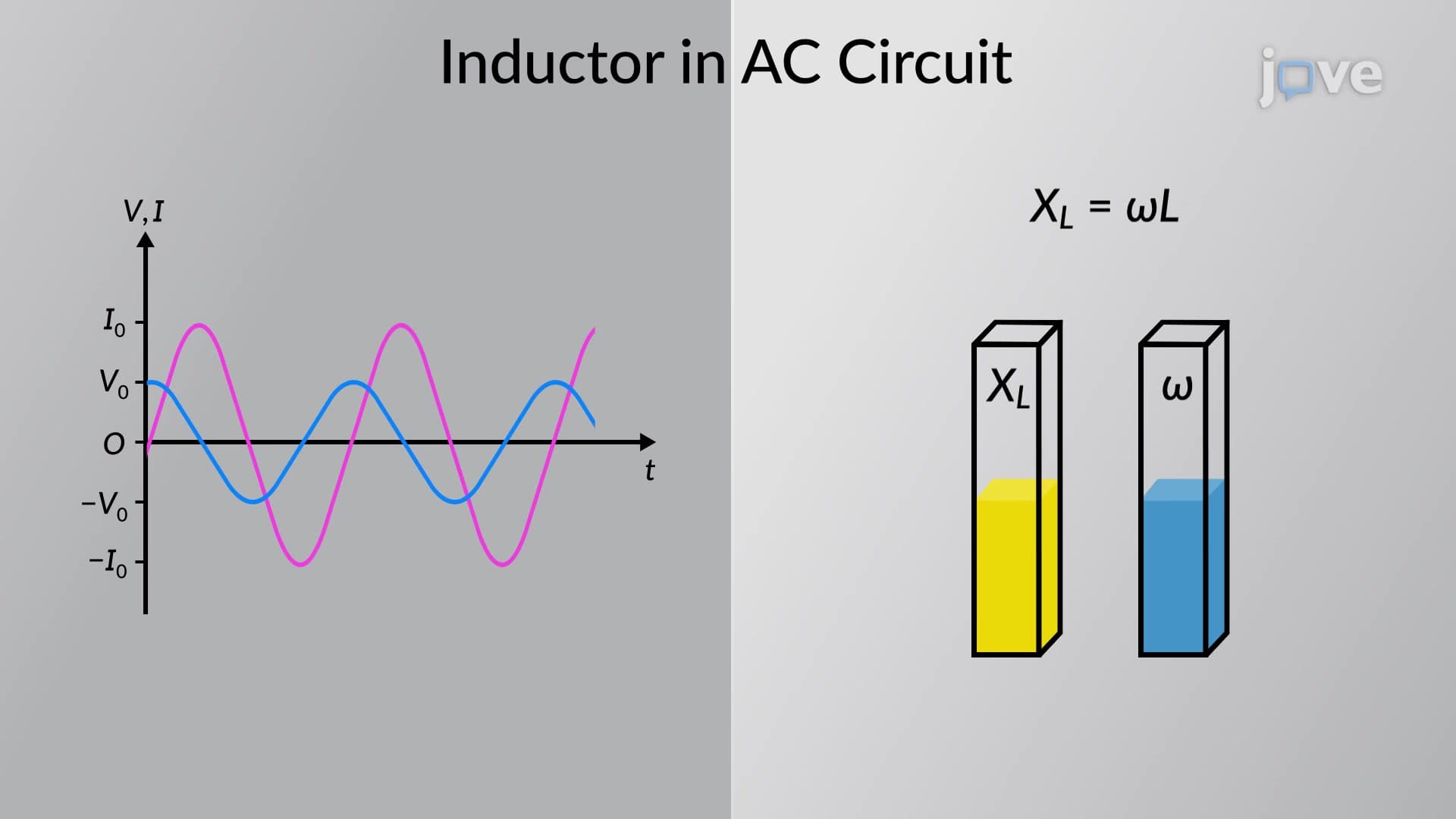
5. Inductive Reactance and Lagging Current Inductors create reactance that increases with frequency, causing current to lag voltage by 90 degrees. This behavior is fundamental to understanding transformers, motors, and other magnetic devices common in American electrical infrastructure. Inductive reactance XL = 2πfL explains why fluorescent light ballasts and motor starting circuits behave differently at various frequencies. The lagging current characteristic is crucial for power factor considerations in industrial settings.
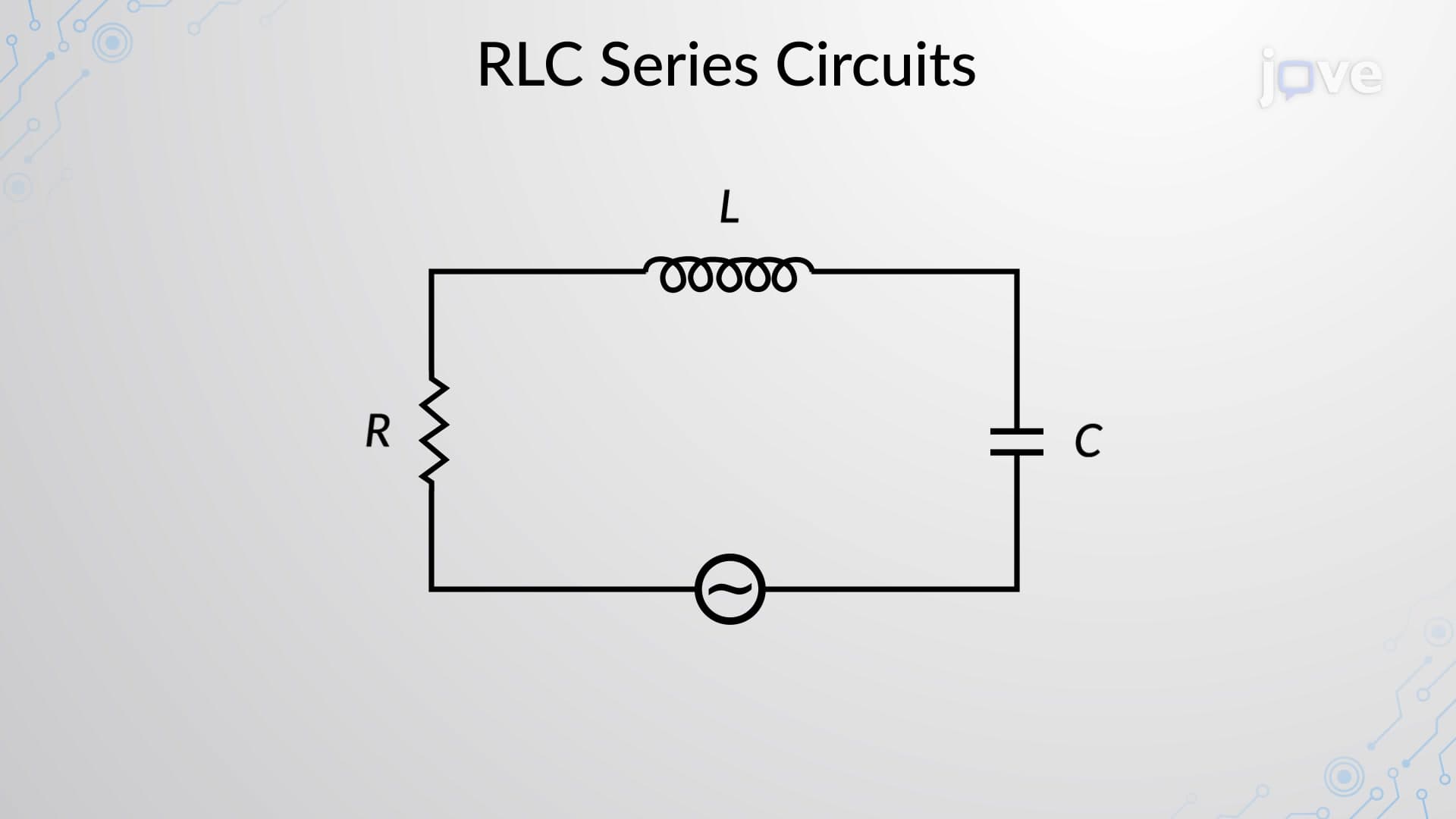
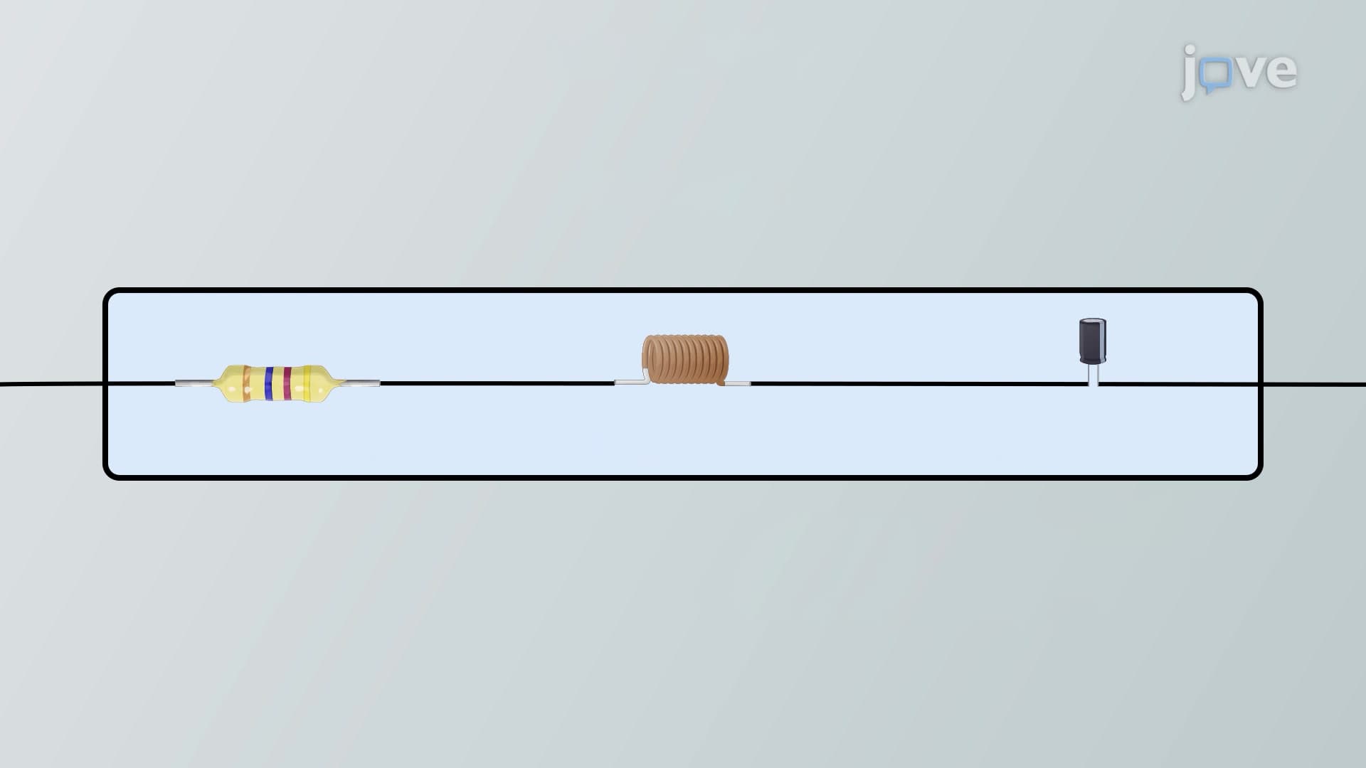
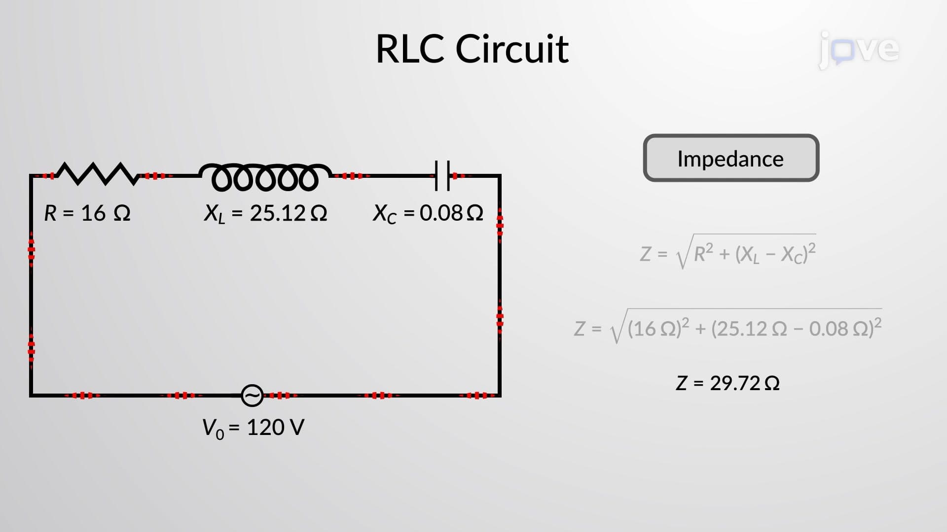
6. RLC Circuit Analysis and Impedance Calculations Series RLC circuits combine resistive, capacitive, and inductive effects into a single impedance value. The analysis of alternating-current circuits requires vector addition of these components since voltage and current relationships involve different phase angles. Impedance Z = √(R² + (XL - XC)²) provides the total opposition to current flow. This concept is essential for designing filters, tuned circuits, and understanding power transmission systems used throughout the US electrical grid.
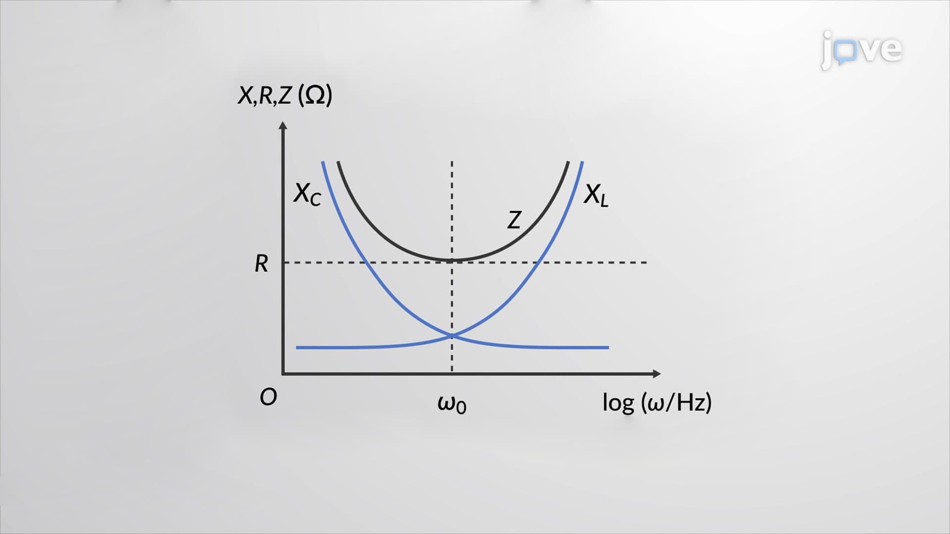
7. Resonance Phenomena and Quality Factor Resonance AC occurs when inductive and capacitive reactances equal each other, creating minimum impedance and maximum current flow. At the resonance frequency f₀ = 1/(2π√LC), the circuit behaves purely resistively. This principle is fundamental to radio tuning circuits, wireless charging systems, and many communication devices used daily in America. The quality factor Q determines the sharpness of resonance, affecting bandwidth and selectivity in electronic applications.
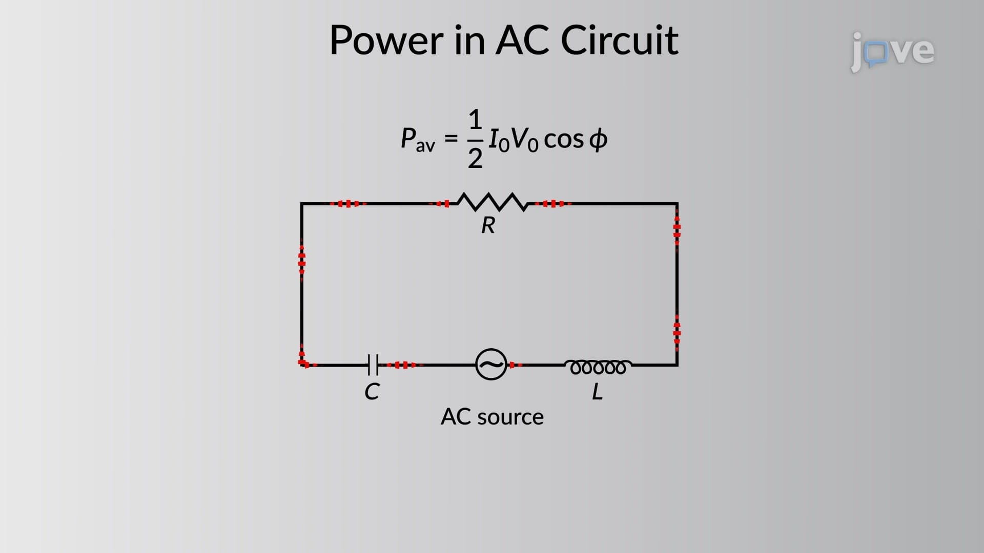
8. AC Power Calculations and Power Factor Power in AC circuits involves both real power (watts) and reactive power (VARs), with the power factor representing their relationship. Real power performs useful work, while reactive power maintains electromagnetic fields without contributing to energy transfer. American utility companies monitor power factor because poor values reduce transmission efficiency. The power factor cos φ relates to the phase angle between voltage and current, making it crucial for industrial power management.
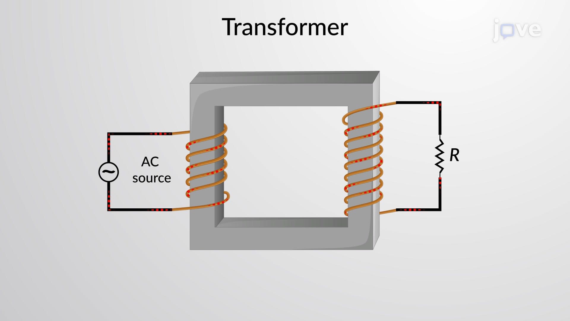
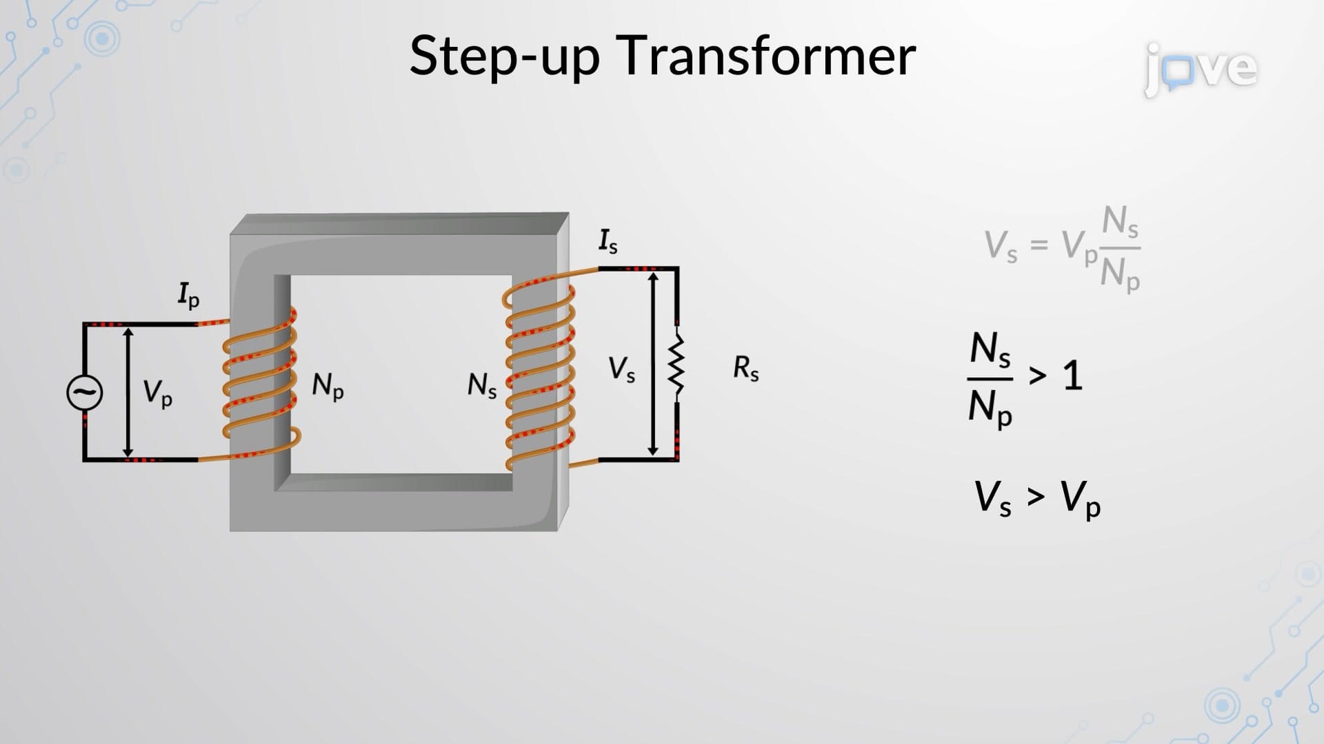
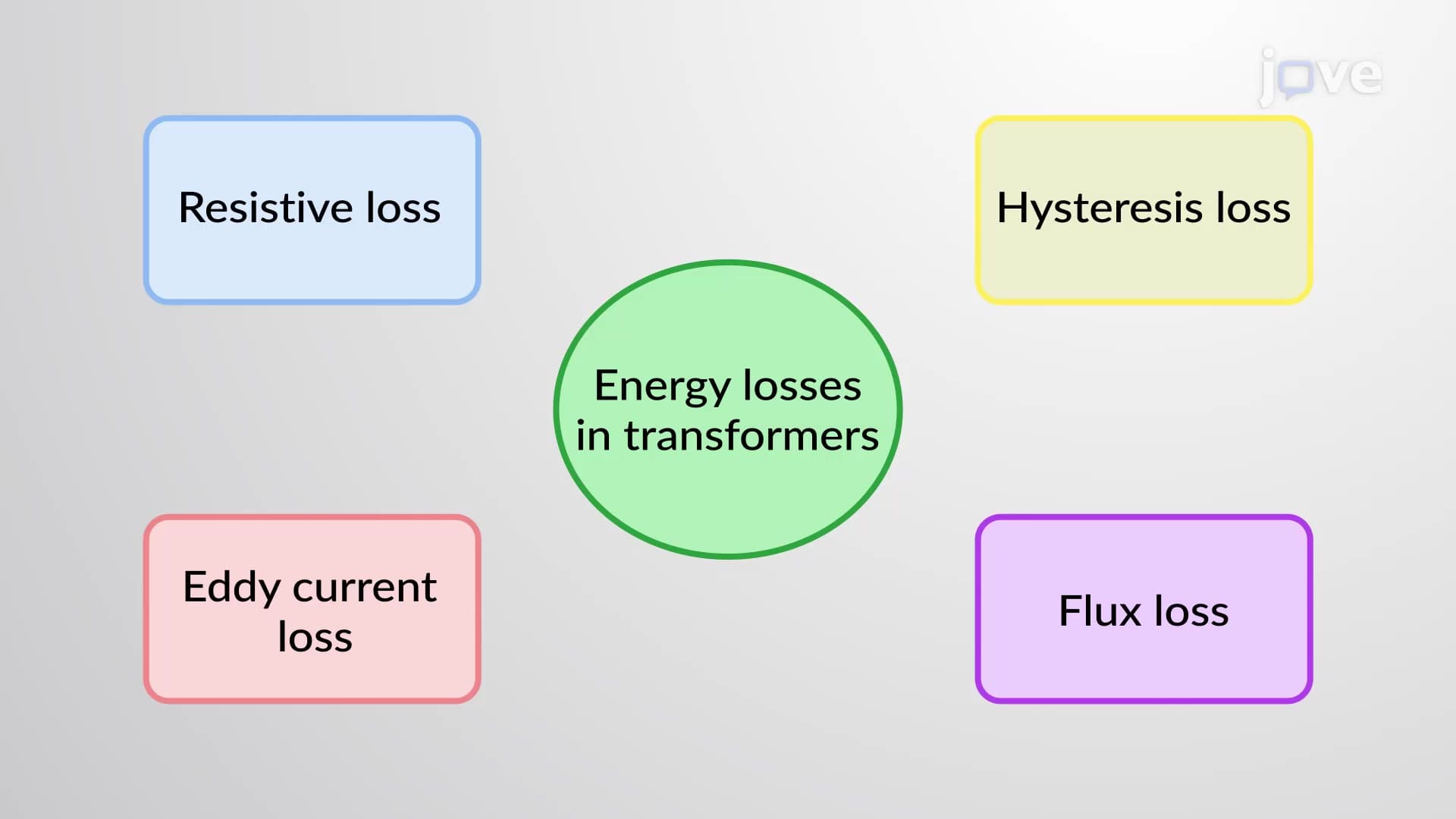
9. Transformer Principles and Applications Transformers enable efficient AC voltage transformation through electromagnetic induction, making long-distance power transmission practical. The transformer equation Vs/Vp = Ns/Np relates secondary and primary voltages to their respective winding turns. Step-up transformers increase voltage for transmission, while step-down transformers reduce it for safe household use. Understanding transformer losses-including resistive, eddy current, hysteresis, and flux losses-is essential for designing efficient power distribution systems like those used across the United States.