Loading video…


 13 Concepts
 29.6K views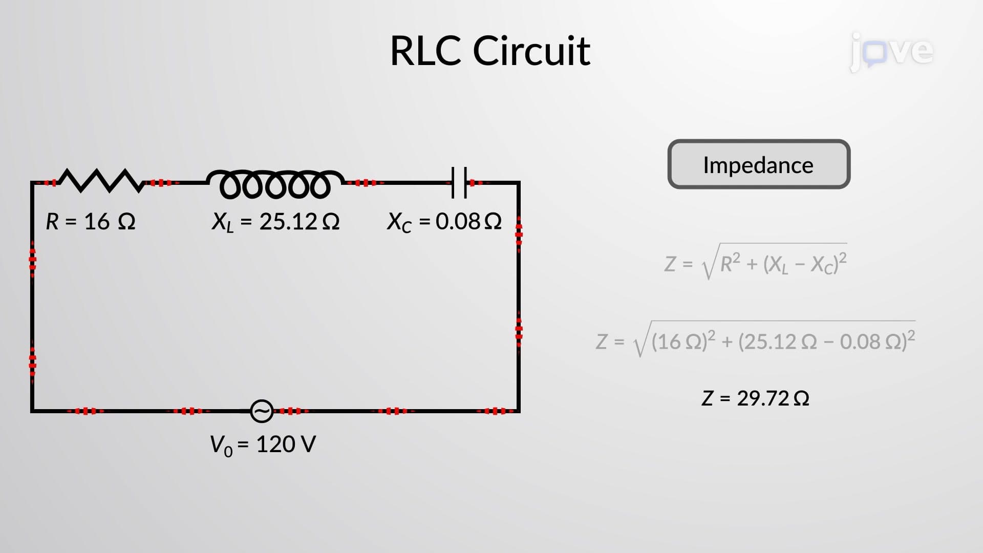

Video Summary: Rlc Series Circuit Problem Solving Explained
Ever wonder why electrical engineers at companies like General Electric can predict exactly how much current flows through complex power systems? RLC series circuit problem solving is the fundamental skill that makes this precision possible, combining resistors, inductors, and capacitors into predictable electrical behaviors. This comprehensive tutorial demonstrates how to calculate impedance, phase angles, and voltage amplitudes across each circuit element using systematic problem-solving approaches. Watch the full video on JoVE Coach to master this concept with expert-led visuals and step-by-step explanations.
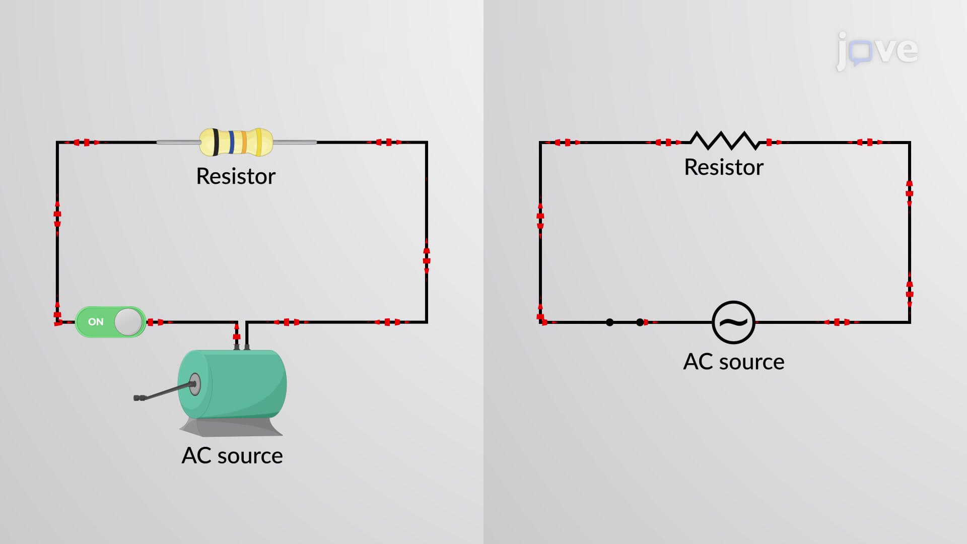
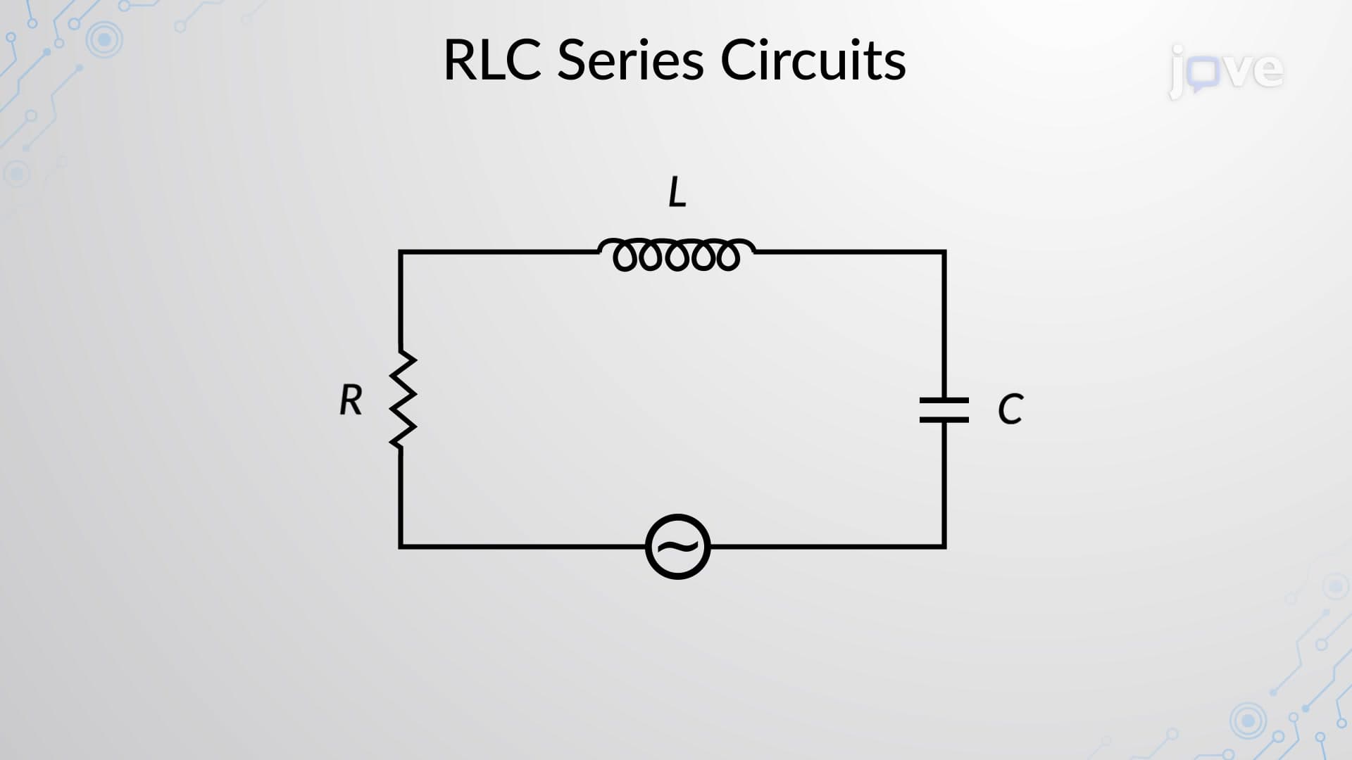
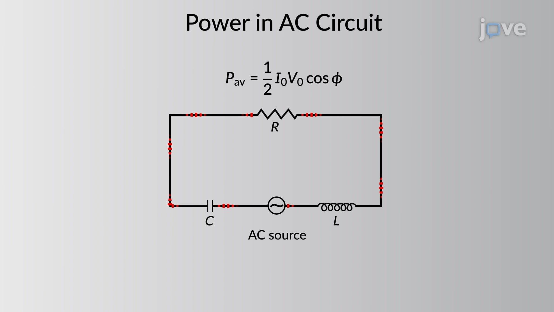
RLC series circuit problem solving represents one of the most practical applications of AC circuit analysis in electrical engineering. When a resistor (R), inductor (L), and capacitor (C) are connected in series with an AC voltage source, they create complex interactions that require systematic mathematical analysis. This approach forms the backbone of power system design at utilities like Pacific Gas & Electric and Tesla's charging infrastructure.
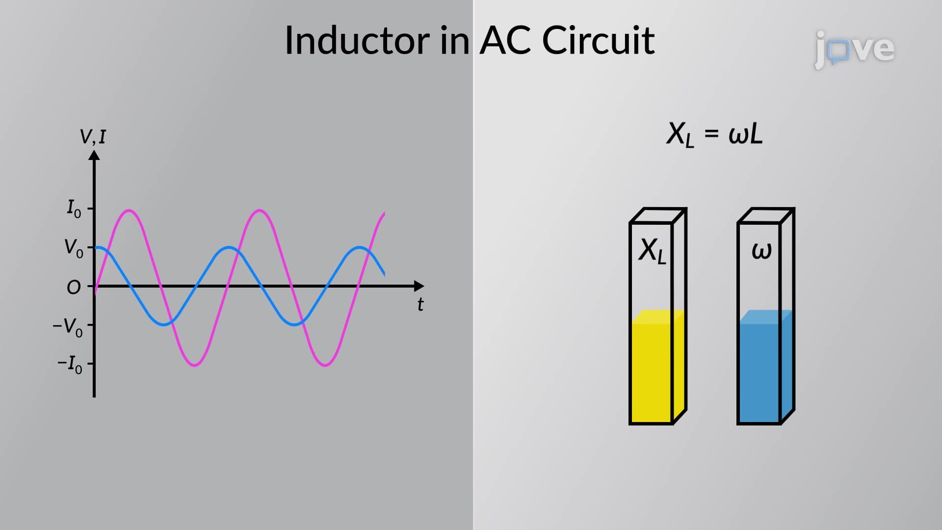
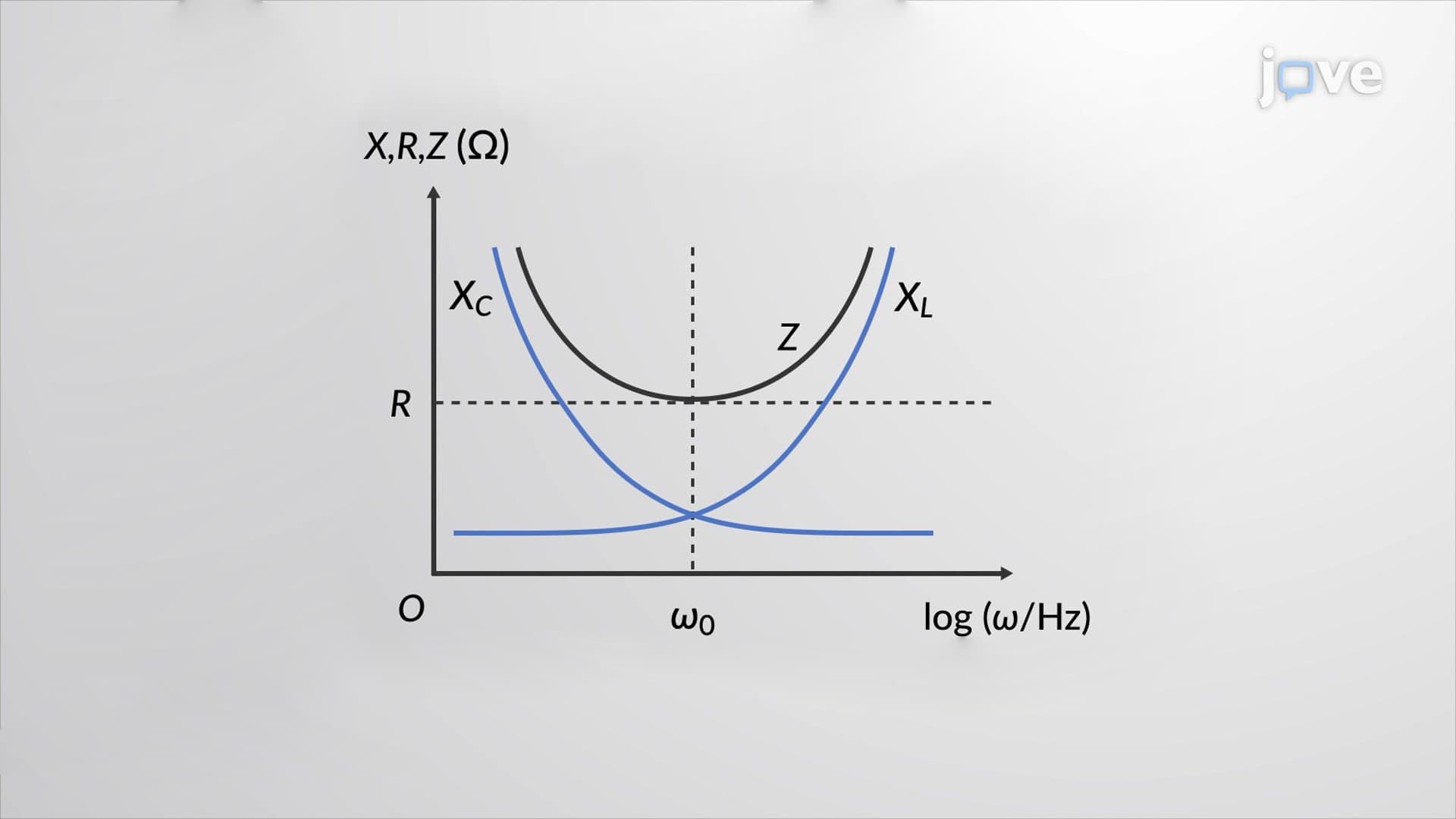
The foundation of successful problem solving begins with calculating reactances. Inductive reactance follows XL = 2πfL, where frequency and inductance determine how strongly the inductor opposes current changes. Capacitive reactance uses XC = 1/(2πfC), showing the inverse relationship between frequency and capacitive opposition. Students preparing for the AP Physics C exam must master these relationships, as they frequently appear in both multiple-choice and free-response sections.
Total impedance combines resistance and net reactance using Z = √(R² + (XL - XC)²), creating the circuit's overall opposition to AC current. The phase angle θ = arctan((XL - XC)/R) reveals whether the circuit behaves inductively (positive angle) or capacitively (negative angle). This concept proves essential for electrical engineering students at universities like MIT or Stanford, where power factor calculations determine system efficiency.
Once impedance is known, current amplitude follows I = V/Z, directly applying Ohm's law to AC circuits. Individual element voltages multiply current by respective impedances: VR = IR, VL = IXL, and VC = IXC. These calculations appear regularly on MCAT physics sections and electrical engineering midterms, where students must demonstrate both conceptual understanding and computational accuracy. Understanding these relationships prepares students for advanced courses in circuit analysis and electromagnetic theory.
Related Micro-courses