Loading video…


 13 Concepts
 29.6K views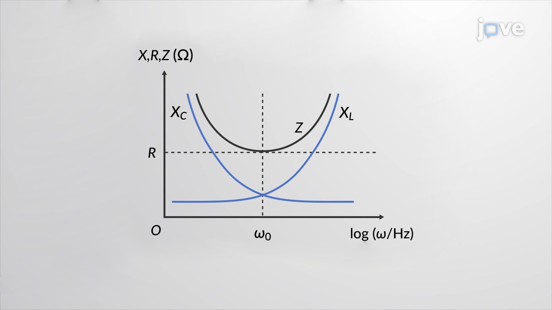

Video Summary: Resonance in an Ac Circuit Explained
Why do radio stations tune to specific frequencies, and what makes some circuits incredibly efficient at those exact frequencies? Resonance in an AC circuit occurs when inductive and capacitive reactances perfectly cancel each other out, creating maximum current flow. Consider AM radio stations broadcasting at 1010 kHz-your car's antenna circuit must achieve resonance at that precise frequency to receive clear audio. This fundamental electrical engineering principle explains how everything from radio receivers to medical MRI machines operates with peak efficiency. Watch the full video on JoVE Coach to master this concept with expert-led visuals and step-by-step explanations.
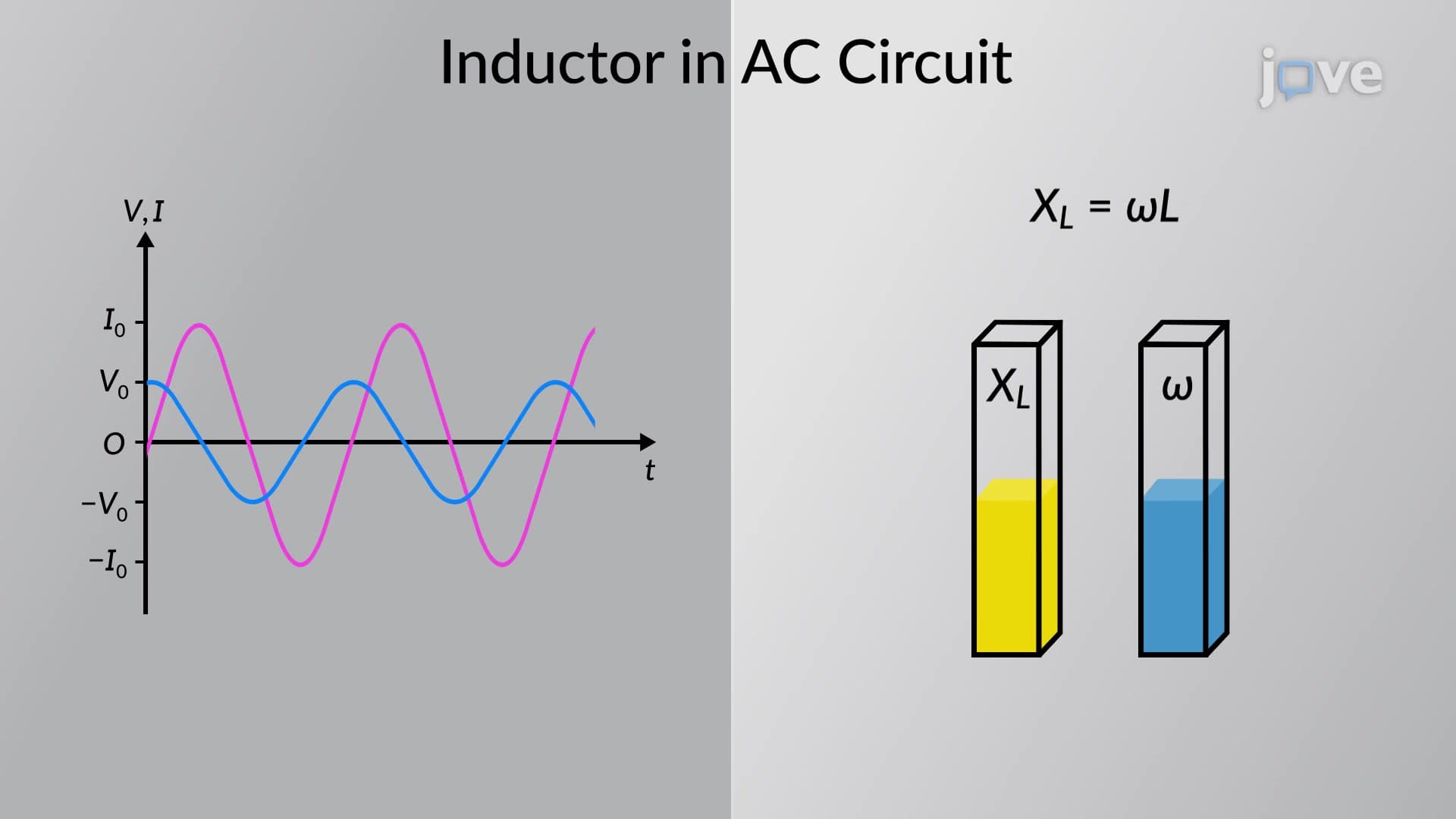
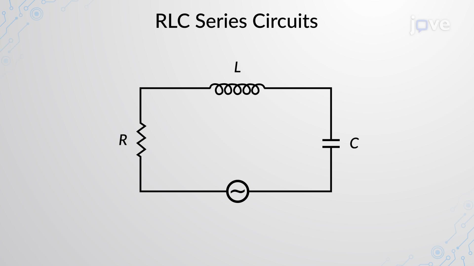
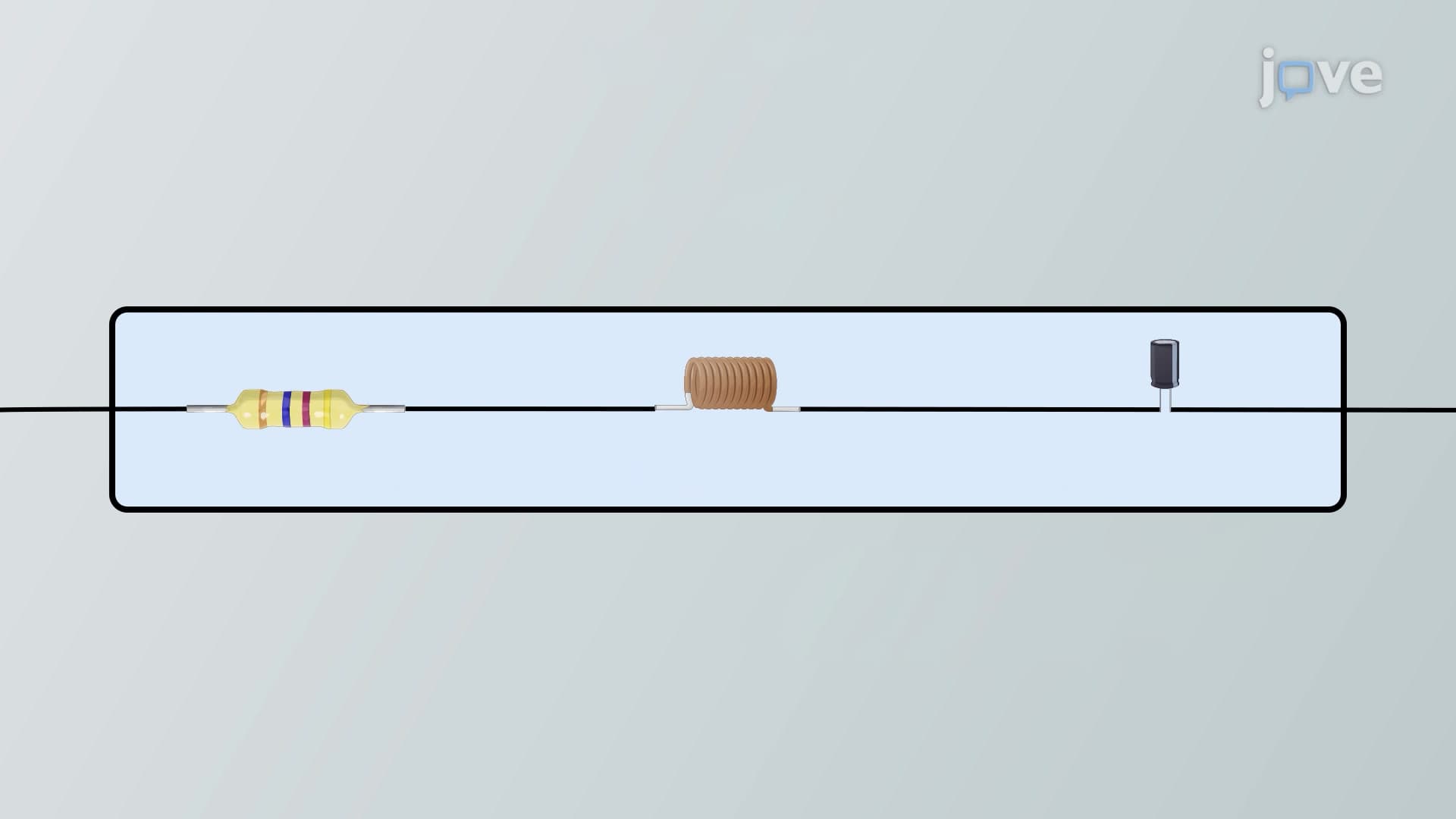
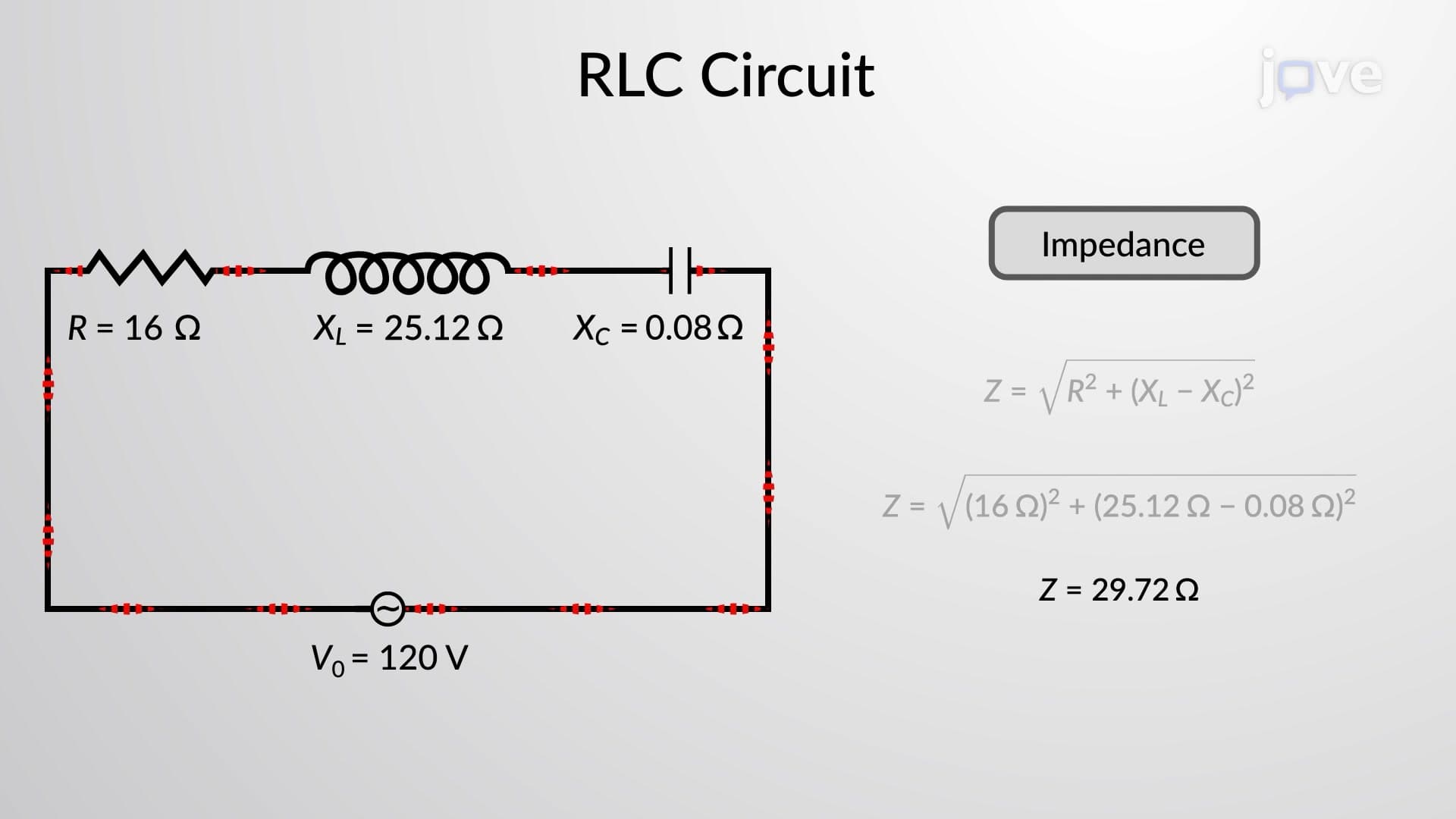
Resonance in an AC circuit represents one of the most elegant phenomena in electrical engineering, occurring when a circuit's natural frequency matches the applied AC source frequency. In a series RLC circuit containing resistance (R), inductance (L), and capacitance (C), this magical moment happens when the inductive reactance (XL = 2πfL) exactly equals the capacitive reactance (XC = 1/(2πfC)).
At resonance, these opposing reactances cancel each other completely, leaving only the pure resistance to oppose current flow. The mathematical condition XL = XC yields the resonance frequency: f₀ = 1/(2π√(LC)). This frequency depends solely on the inductance and capacitance values, making it predictable and controllable for engineering applications.
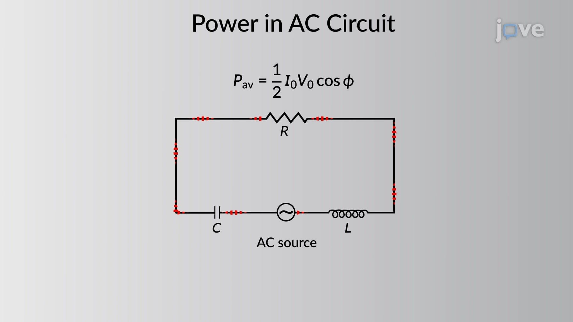
When operating at resonance frequency, the circuit exhibits several remarkable characteristics. The total impedance reaches its minimum value, equaling just the resistance: Z = R. This minimum impedance allows maximum current flow, following Ohm's law: I = V/R. The phase difference between voltage and current becomes zero, meaning they oscillate perfectly in sync-a condition called "unity power factor."
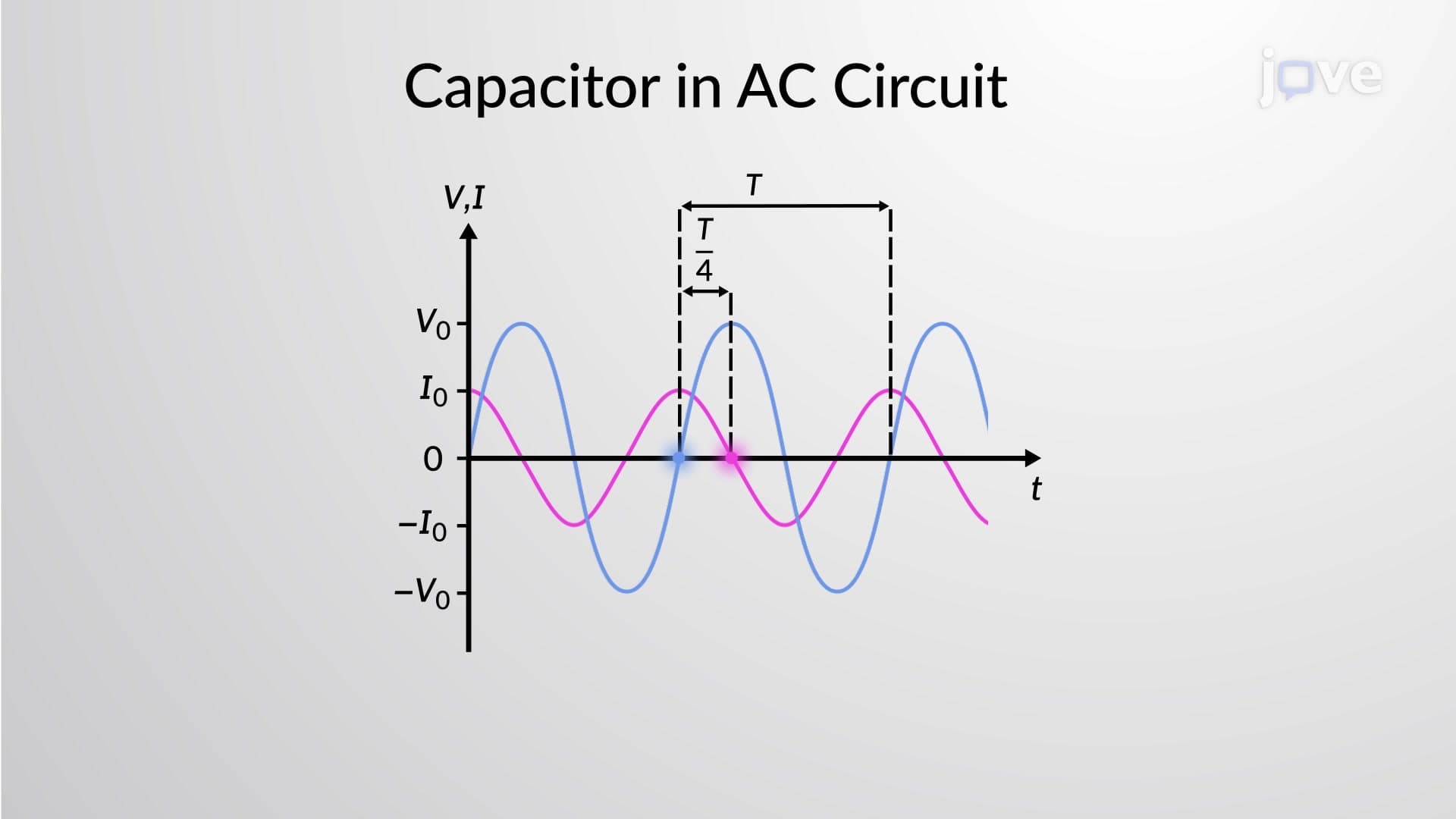
Students preparing for AP Physics C or college-level circuit analysis should remember that below resonance frequency, capacitive reactance dominates, making current lead voltage. Above resonance, inductive reactance takes control, causing current to lag behind voltage. This frequency-dependent behavior appears regularly on standardized exams and engineering coursework.
The quality factor (Q) quantifies how "sharp" or selective a resonant circuit behaves. Mathematically, Q = f₀/BW, where BW represents the bandwidth-the frequency range where power exceeds half its maximum value. Higher Q values create narrower bandwidths and sharper resonance peaks, while lower Q values produce broader, more forgiving frequency responses.
For practical applications, Q = (1/R)√(L/C), revealing that lower resistance increases selectivity. This relationship explains why high-quality inductors and capacitors (with minimal internal resistance) create superior radio receivers and filter circuits.
Resonance principles power countless American technologies. AM radio receivers use resonant circuits tuned to specific broadcast frequencies (540-1600 kHz band). Tesla's wireless charging stations employ resonant coupling between transmitter and receiver coils at precisely matched frequencies around 85 kHz. Medical MRI machines generate their powerful magnetic fields using resonant LC circuits operating at radio frequencies.
Engineering students encounter these concepts in courses like EE 101 at MIT or ECE fundamentals at Stanford University. MCAT test-takers see simplified versions in physics sections, while AP Physics C exams frequently include resonance calculations and conceptual questions.
Related Micro-courses