Loading video…


 13 Concepts
 29.6K views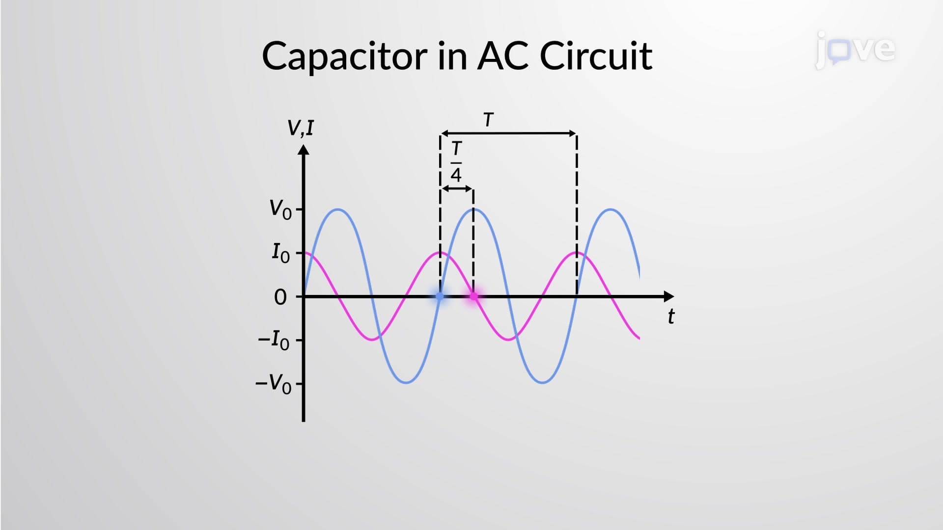

Video Summary: Capacitor in an Ac Circuit Explained
Ever wonder why the power grid in your smartphone charger can deliver steady DC power from alternating AC wall outlets? A capacitor in an AC circuit behaves fundamentally differently than in DC circuits, creating a phase relationship where current leads voltage by 90 degrees. This phenomenon explains how power supplies, audio equipment, and even Tesla coils function in American homes and laboratories. Watch the full video on JoVE Coach to master this concept with expert-led visuals and step-by-step explanations.
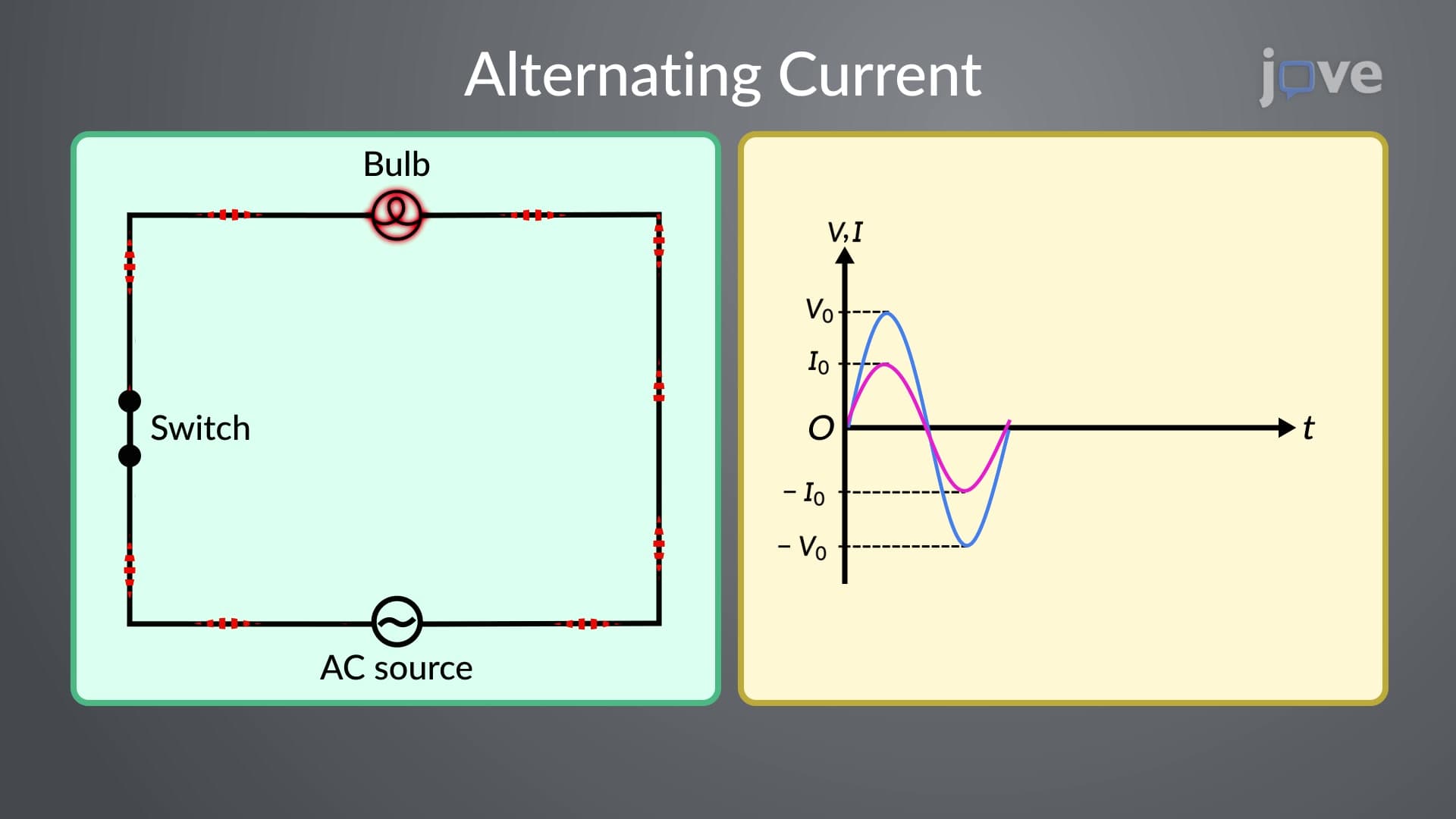
When a capacitor connects to an alternating current source, it exhibits behavior that distinguishes it from resistive elements. Unlike DC circuits where capacitors eventually block current flow, AC circuits allow continuous current flow through capacitive elements due to the constantly changing electric field.
The fundamental principle governing this behavior stems from the capacitor's defining relationship: Q = CV. As the AC voltage changes sinusoidally, the charge on the capacitor plates must also change. This changing charge creates current flow in the external circuit, even though no charge physically crosses the dielectric gap between plates.
The most crucial characteristic of capacitor behavior in AC circuits is the phase relationship between current and voltage. Mathematical analysis reveals that current leads voltage by exactly 90 degrees (π/2 radians). This occurs because current equals the rate of charge change (I = dQ/dt), and when voltage follows a cosine function, current follows a sine function-shifted ahead by one quarter cycle.
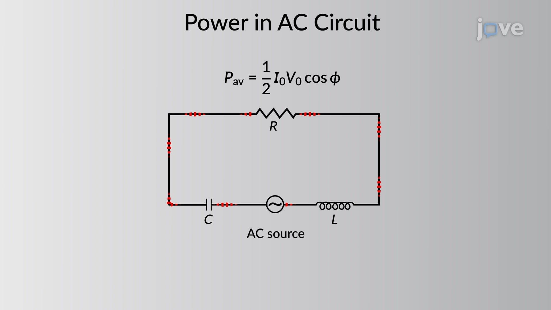
This phase relationship explains why capacitors can store and release energy cyclically in AC circuits. During one quarter of the AC cycle, the capacitor charges and stores energy. During the next quarter, it discharges this energy back to the circuit. This behavior makes capacitors essential in power factor correction systems used throughout US electrical infrastructure.
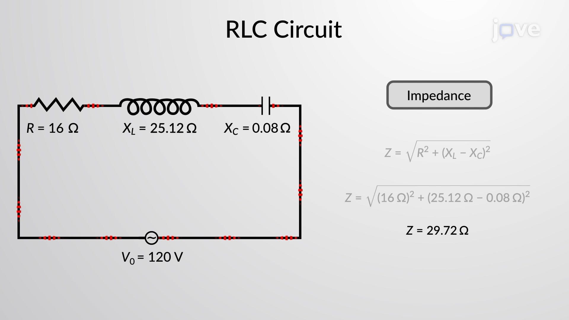
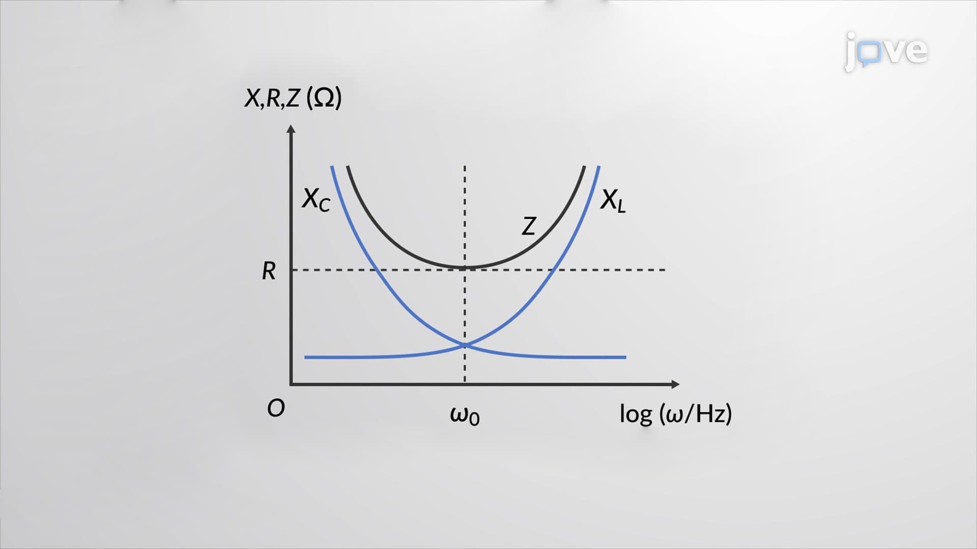
Capacitive reactance (X_C) represents the opposition a capacitor presents to AC current flow, measured in ohms like resistance. The relationship X_C = 1/(2πfC) shows that reactance decreases as frequency increases. This inverse relationship has profound practical implications.
At low frequencies approaching DC, capacitive reactance becomes very large, effectively blocking current. At high frequencies, reactance drops significantly, allowing easier current flow. This frequency-dependent behavior enables capacitors to function as filters in audio equipment, blocking low-frequency noise while passing high-frequency signals.
US students encounter capacitive reactance concepts in AP Physics courses, college circuits courses, and professional exams like the FE (Fundamentals of Engineering). Understanding these principles proves essential for analyzing power supplies in consumer electronics, motor starting circuits in HVAC systems, and signal processing in telecommunications equipment manufactured by companies like Intel and Qualcomm.
Related Micro-courses