Loading video…


 13 Concepts
 29.6K views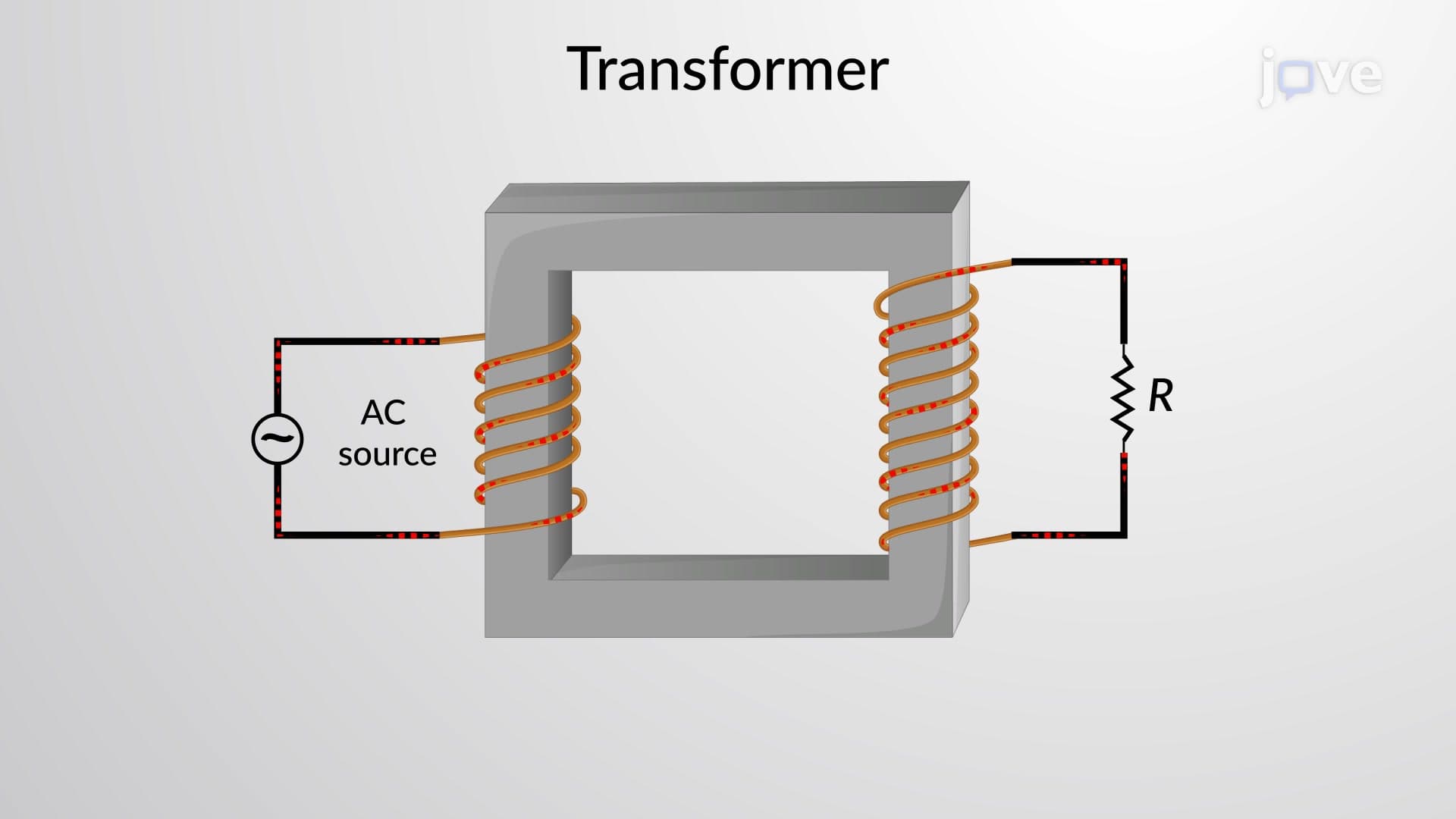

Video Summary: What are Transformers
Ever wondered how electricity travels thousands of miles from power plants to charge your phone without losing voltage? Transformers make this possible by transferring electrical energy between circuits through electromagnetic induction. These devices increase or decrease AC voltage while maintaining constant frequency, powering everything from Tesla charging stations to your home's electrical grid. Understanding what transformers are and how they work is fundamental to electrical engineering and physics. Watch the full video on JoVE Coach to master this concept with expert-led visuals and step-by-step explanations.
Transformers represent one of the most ingenious applications of electromagnetic induction in electrical engineering. At their essence, these devices enable the efficient transfer of electrical energy between two or more circuits without direct electrical connection. This wireless energy transfer occurs through the phenomenon of electromagnetic induction, discovered by Michael Faraday in the 1830s.
The fundamental principle involves alternating current in the primary winding creating a changing magnetic field in the iron core. This changing magnetic flux then induces an electromotive force (EMF) in the secondary winding, effectively transferring energy from one circuit to another. This process maintains the frequency of the alternating current while allowing voltage and current levels to be modified according to the turns ratio.
Transformers come in various configurations, but all share common structural elements. The core consists of laminated soft iron sheets that provide a low-reluctance path for magnetic flux while minimizing eddy current losses. The primary winding connects to the AC source, while the secondary winding connects to the load.
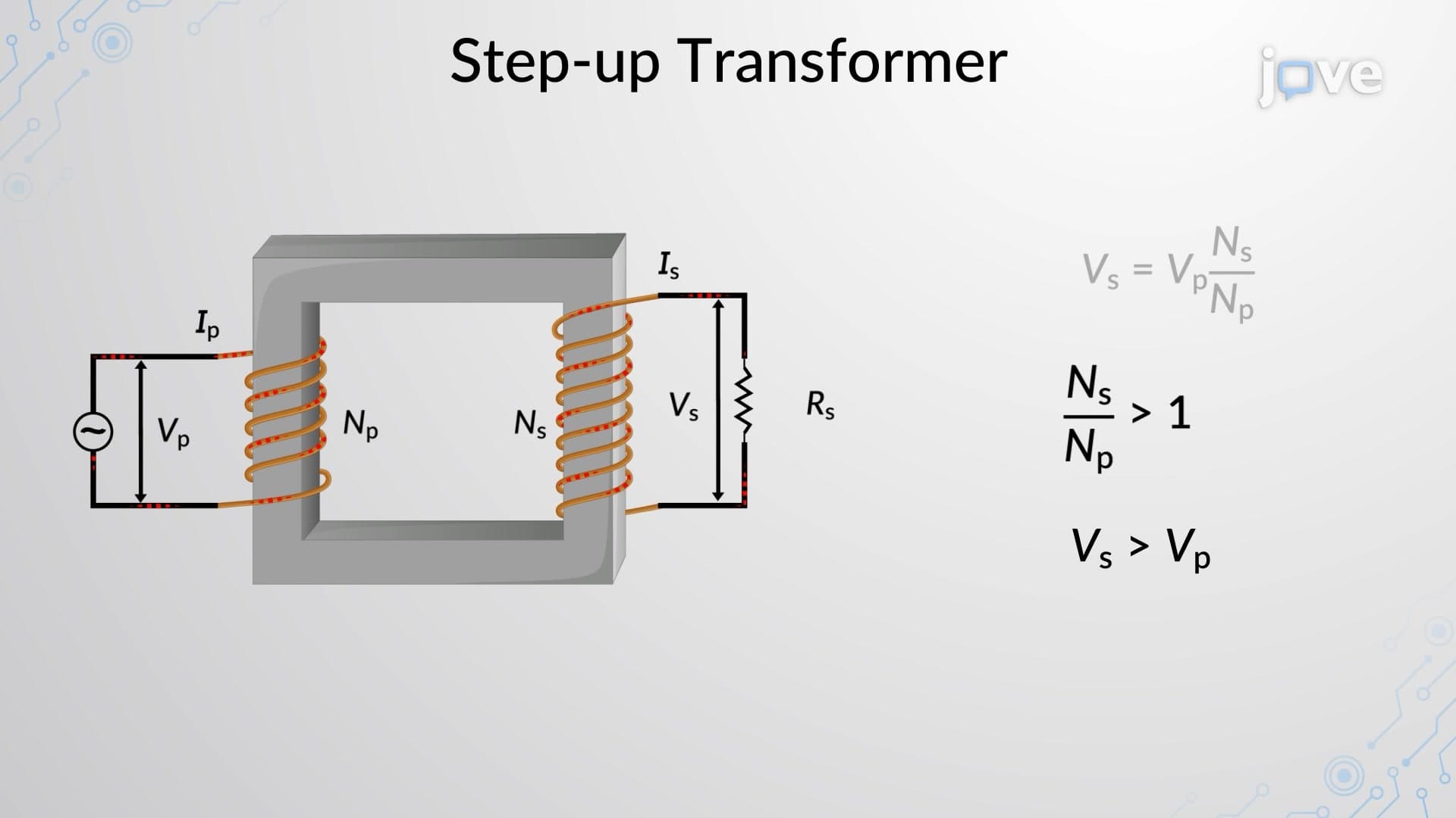
Step-up transformers increase voltage by having more turns in the secondary winding than the primary (Ns > Np). These are essential in power transmission systems, where electricity generated at 25,000 volts is stepped up to 765,000 volts for long-distance transmission across states. Conversely, step-down transformers reduce voltage for safe residential use, bringing high transmission voltages down to the standard 120V found in American homes.
Distribution transformers mounted on utility poles throughout neighborhoods typically step down 7,200V to 240V for residential service. Meanwhile, isolation transformers provide electrical isolation between circuits without changing voltage levels, crucial for medical equipment safety in hospitals.
The transformer equation governs the voltage relationship: Vs/Vp = Ns/Np, where V represents voltage and N represents the number of turns in each winding. For ideal transformers (assuming no losses), the power input equals power output: VpIp = VsIs. This means current relationships follow the inverse ratio: Is/Ip = Np/Ns.
These relationships are fundamental in AP Physics courses and appear frequently on college electrical engineering exams. Students often encounter transformer problems on the SAT Physics Subject Test, where they must calculate unknown voltages or currents using turns ratios.
Power distribution represents the most visible transformer application. The entire electrical grid depends on transformer networks stepping voltage up for efficient transmission and down for safe utilization. Electric vehicle charging stations use transformers to convert high-voltage AC from the grid to appropriate DC charging levels.
In electronics, small transformers in power supplies convert 120V AC to lower DC voltages for computers and smartphones. Medical equipment relies on isolation transformers for patient safety, while industrial facilities use large transformers for heavy machinery operation.
Understanding transformers proves essential for MCAT physics sections, electrical engineering coursework, and professional licensing exams for electricians and engineers.
Related Micro-courses