Loading video…


 13 Concepts
 29.6K views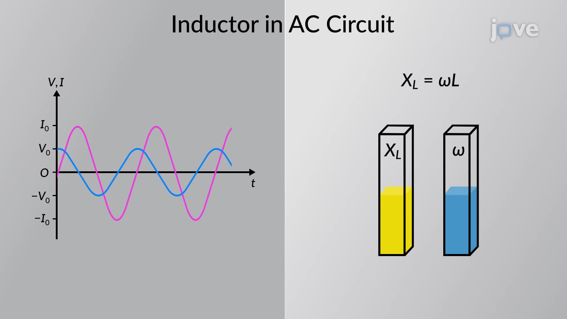

Video Summary: Inductor in an Ac Circuit Explained
Why does the humming sound from electrical transformers change pitch when power demand fluctuates? An inductor in an AC circuit creates fascinating phase relationships that power engineers at companies like General Electric must master. When alternating current flows through an inductor, the current lags behind the voltage by 90 degrees, creating inductive reactance that increases with frequency. Watch the full video on JoVE Coach to master this concept with expert-led visuals and step-by-step explanations.
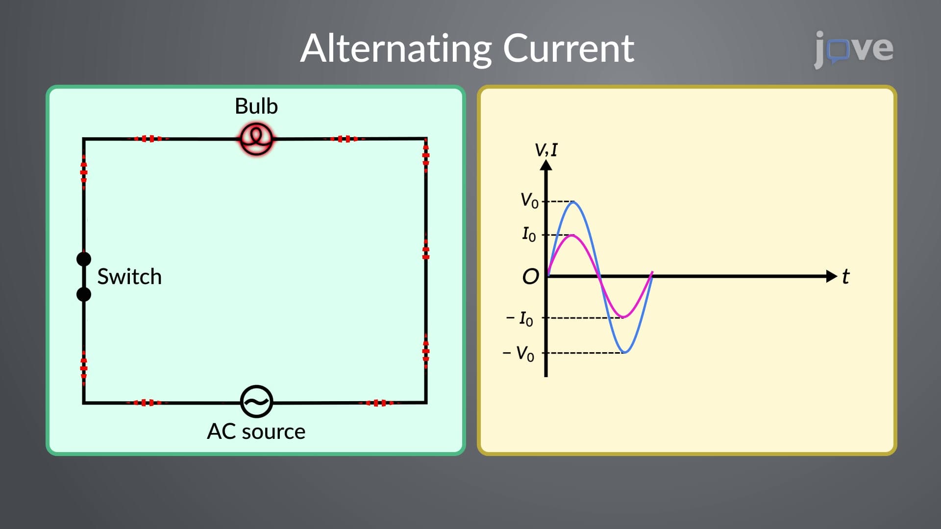
An inductor in an AC circuit exhibits unique behavior that distinguishes it from resistive components. Unlike resistors where current and voltage remain in phase, inductors create a fundamental phase shift due to their electromagnetic properties. When alternating current flows through an inductor's coiled wire, the changing magnetic field generates a back EMF that opposes current changes, following Lenz's law.
The most critical characteristic of inductor behavior in AC circuits is the 90-degree phase lag. Current through the inductor lags the applied voltage by exactly one-quarter cycle (π/2 radians). This relationship becomes essential for students preparing for AP Physics exams and college-level circuit analysis courses. Phasor diagrams provide powerful visualization tools, showing both current and voltage as rotating vectors with identical angular frequency but different phases.
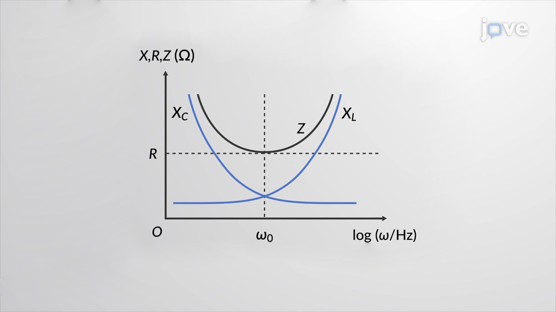
Inductive reactance (XL) represents the inductor's opposition to alternating current, measured in ohms like resistance. The formula XL = 2πfL reveals the direct relationship between reactance, frequency (f), and inductance (L). Higher frequencies produce greater reactance, explaining why inductors effectively block high-frequency signals while allowing low frequencies to pass. This frequency-dependent behavior makes inductors invaluable in filter circuits used throughout American telecommunications infrastructure.
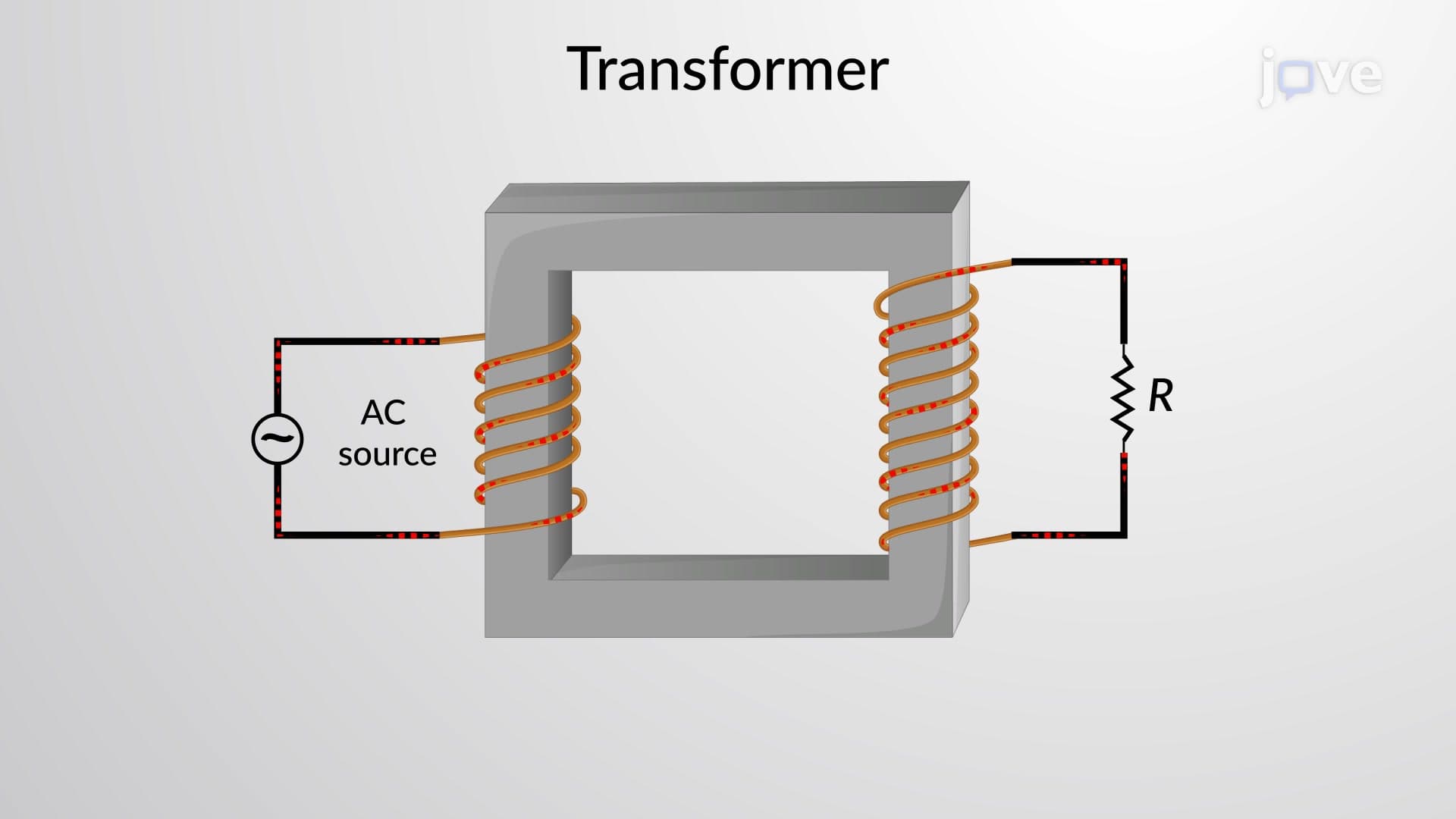
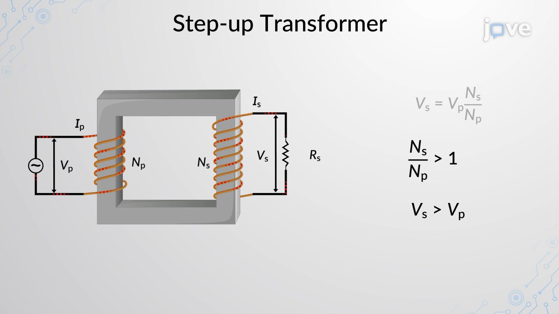
Power transmission systems across the United States rely heavily on inductor behavior in AC circuits. Electrical transformers at substations operate on inductive principles, stepping voltage levels up for efficient long-distance transmission and down for safe residential use. Students encounter these concepts on SAT Subject Tests, AP Physics C exams, and introductory college physics courses. Understanding inductive reactance calculations proves essential for electrical engineering majors tackling circuit analysis problems and power systems coursework at institutions like MIT and Stanford.
Related Micro-courses