Loading video…


 13 Concepts
 29.6K views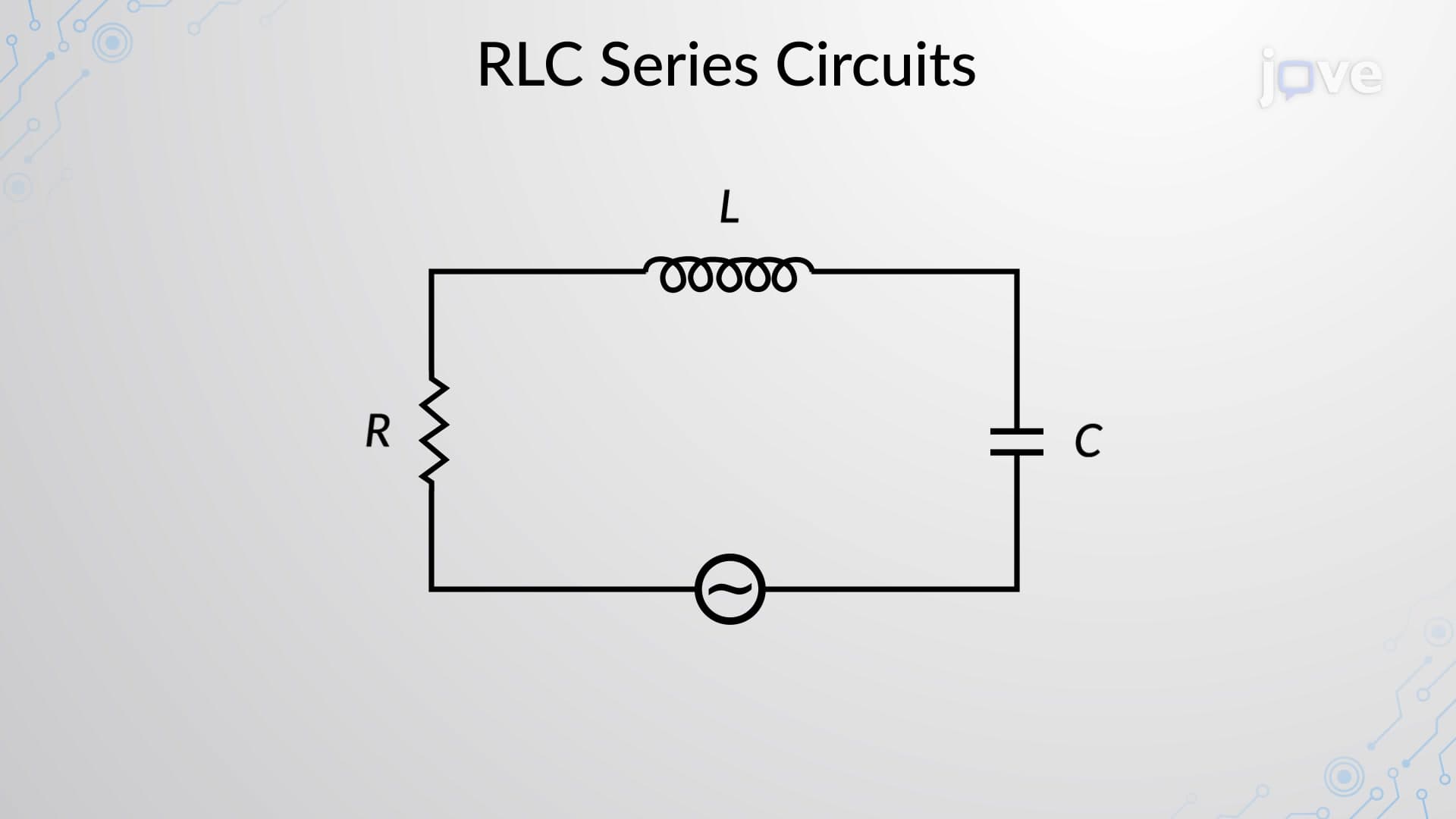

Video Summary: What Is Rlc Series Circuits Introduction
Ever wondered how your smartphone's wireless charging works or why radio antennas need specific lengths? RLC series circuits introduction explains the fundamental behavior when resistors, inductors, and capacitors combine in electrical systems. These circuits power everything from Tesla's wireless charging stations to AM/FM radio transmissions across America. Understanding what is RLC series circuits introduction reveals how voltage and current interact through phase relationships, creating the foundation for modern electronics and power systems. Watch the full video on JoVE Coach to master this concept with expert-led visuals and step-by-step explanations.
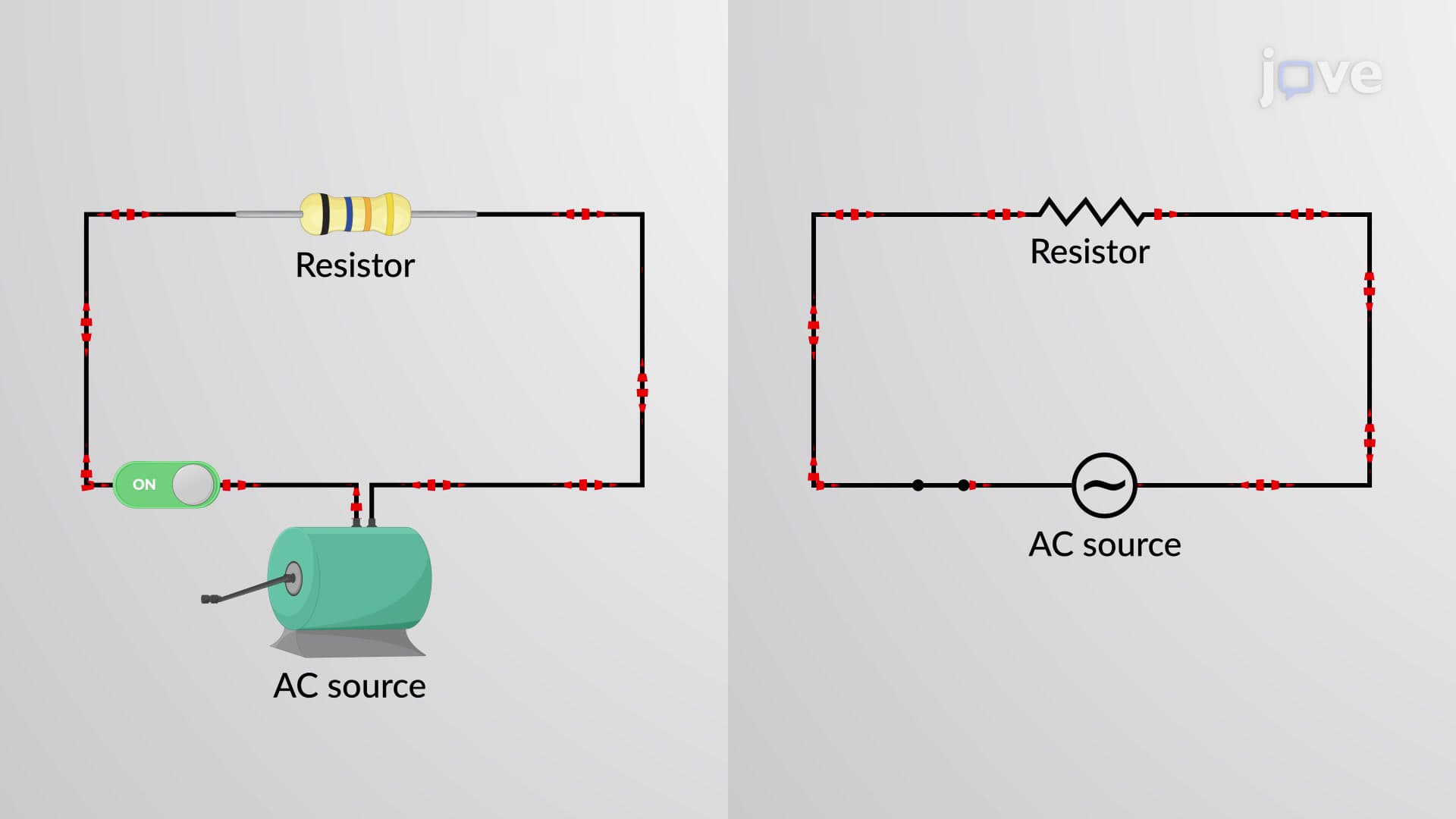
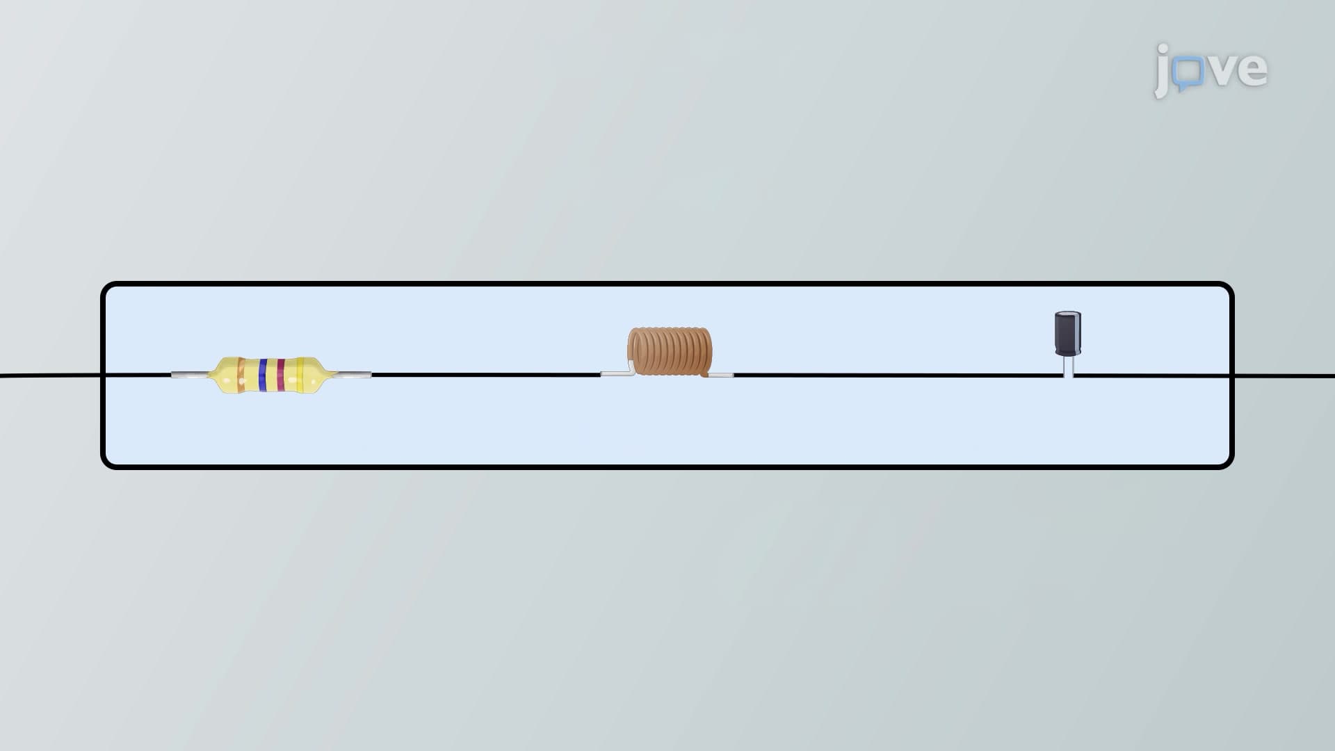
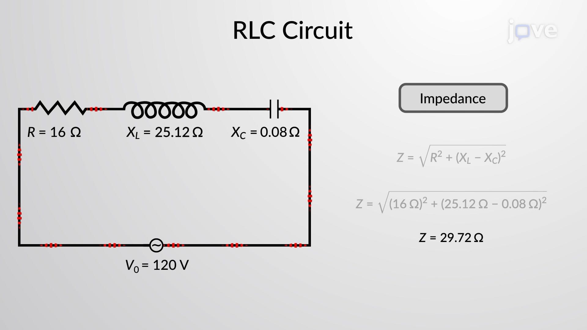
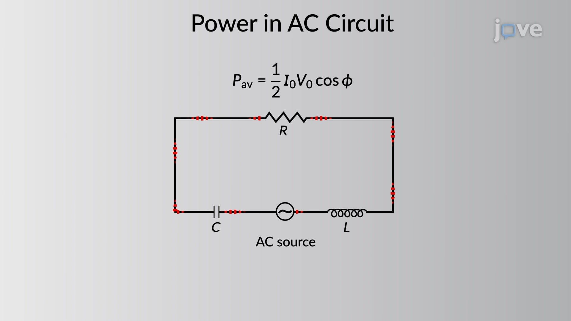
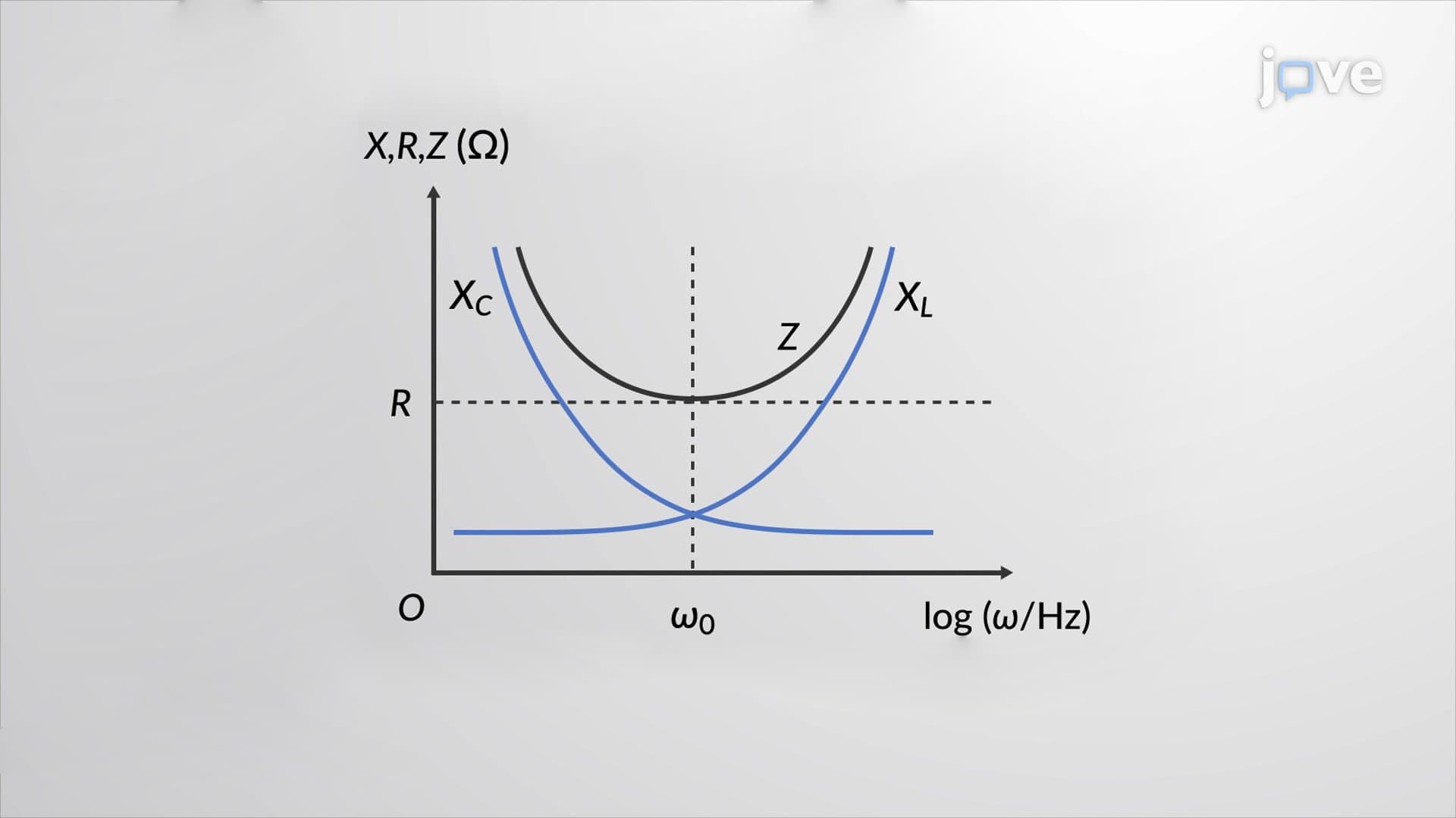
What is RLC series circuits introduction begins with recognizing that these circuits combine three fundamental electrical components in a single current path. Unlike DC circuits where only resistance matters, AC circuits introduce reactance-the opposition to current flow that depends on frequency. When a resistor (R), inductor (L), and capacitor (C) connect in series with an AC voltage source, each component affects the circuit differently, creating complex interactions that form the backbone of modern electrical engineering.
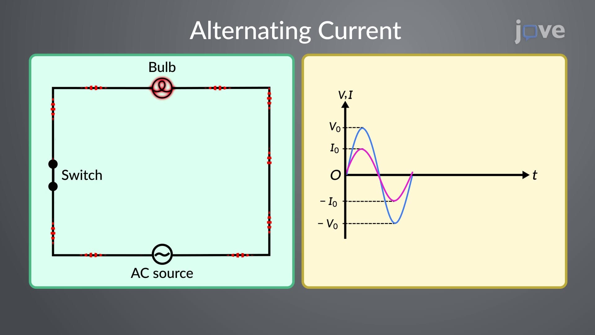
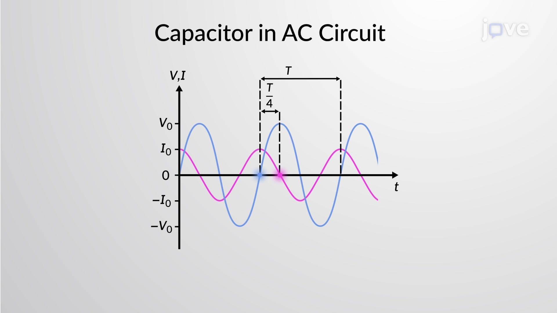
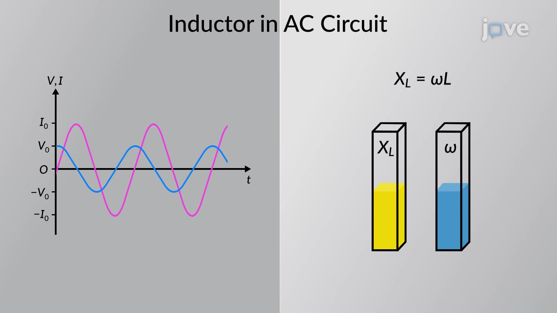
The RLC series circuits introduction concept centers on phase relationships between voltage and current. In purely resistive circuits, voltage and current remain in phase, meaning they reach peak values simultaneously. However, inductors cause voltage to lead current by 90 degrees, while capacitors cause voltage to lag current by 90 degrees. When combined in series, these opposing effects create a net phase difference that determines the circuit's overall behavior-crucial for understanding everything from power grid efficiency to audio amplifier design.
RLC series circuits basics involve phasor diagrams-rotating vectors that represent sinusoidal quantities. These visual tools simplify complex mathematical calculations by converting time-varying voltages and currents into static geometric problems. Students preparing for AP Physics or college-level electrical engineering courses must master phasor addition, where the source voltage phasor equals the vector sum of individual component voltage phasors. This mathematical framework appears frequently on MCAT physics sections and engineering program entrance exams.
The RLC series circuits introduction study guide extends beyond theoretical knowledge to real-world applications. Radio frequency filters in cell phone towers use RLC combinations to separate different communication channels. Power factor correction systems in industrial facilities employ these circuits to improve energy efficiency, potentially saving companies like General Electric millions in utility costs. Understanding these circuits proves essential for students pursuing electrical engineering degrees at institutions like MIT, Stanford, or Georgia Tech, where advanced coursework builds directly on these foundational principles.
Related Micro-courses