Loading video…


 13 Concepts
 29.6K views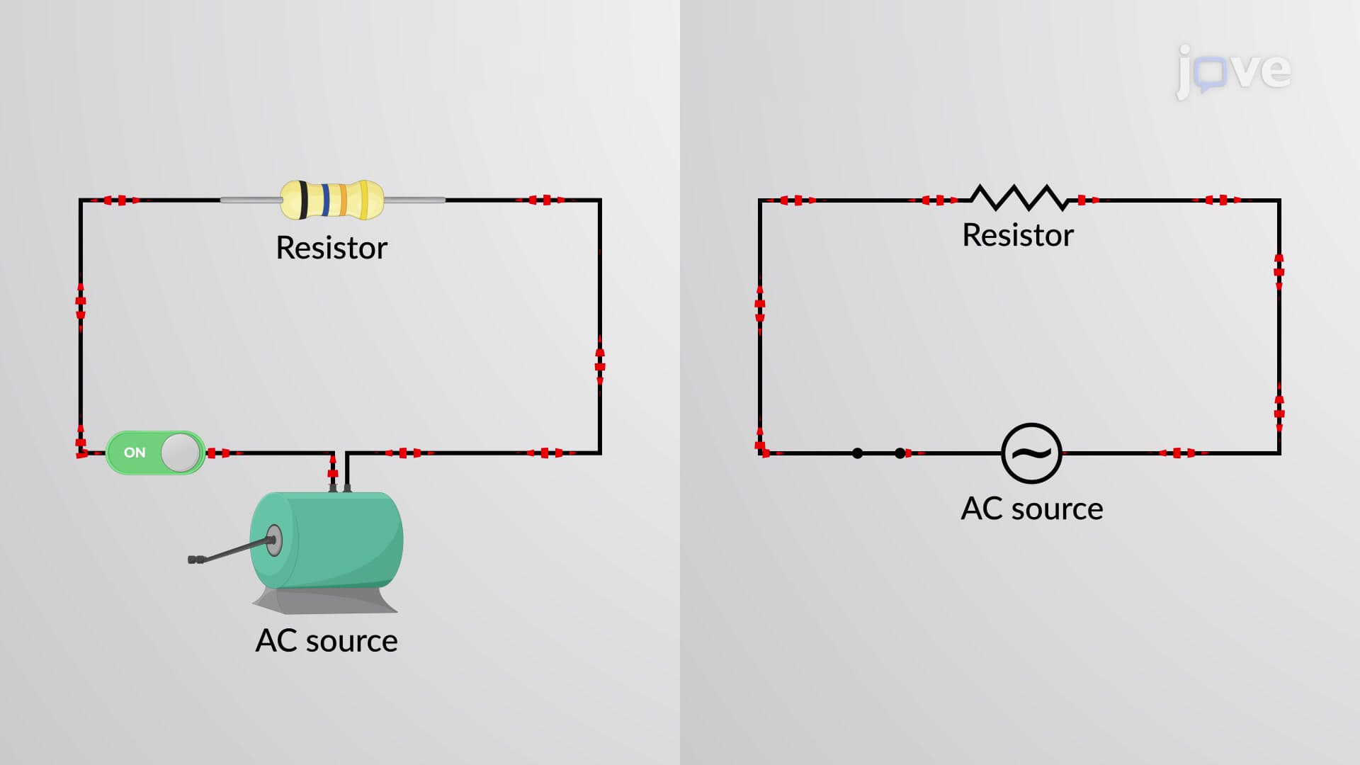

Video Summary: Resistor in an Ac Circuit Explained
Ever wonder why the lights in your home don't flicker despite using alternating current? A resistor in an AC circuit behaves fundamentally differently than in DC circuits, yet maintains a predictable relationship between voltage and current. Unlike capacitors or inductors, resistors create no phase shift in AC circuits-meaning voltage and current reach their peaks simultaneously, much like synchronized swimmers in a US Olympic team. This phase relationship makes resistors the simplest AC components to analyze using phasor diagrams. Watch the full video on JoVE Coach to master this concept with expert-led visuals and step-by-step explanations.
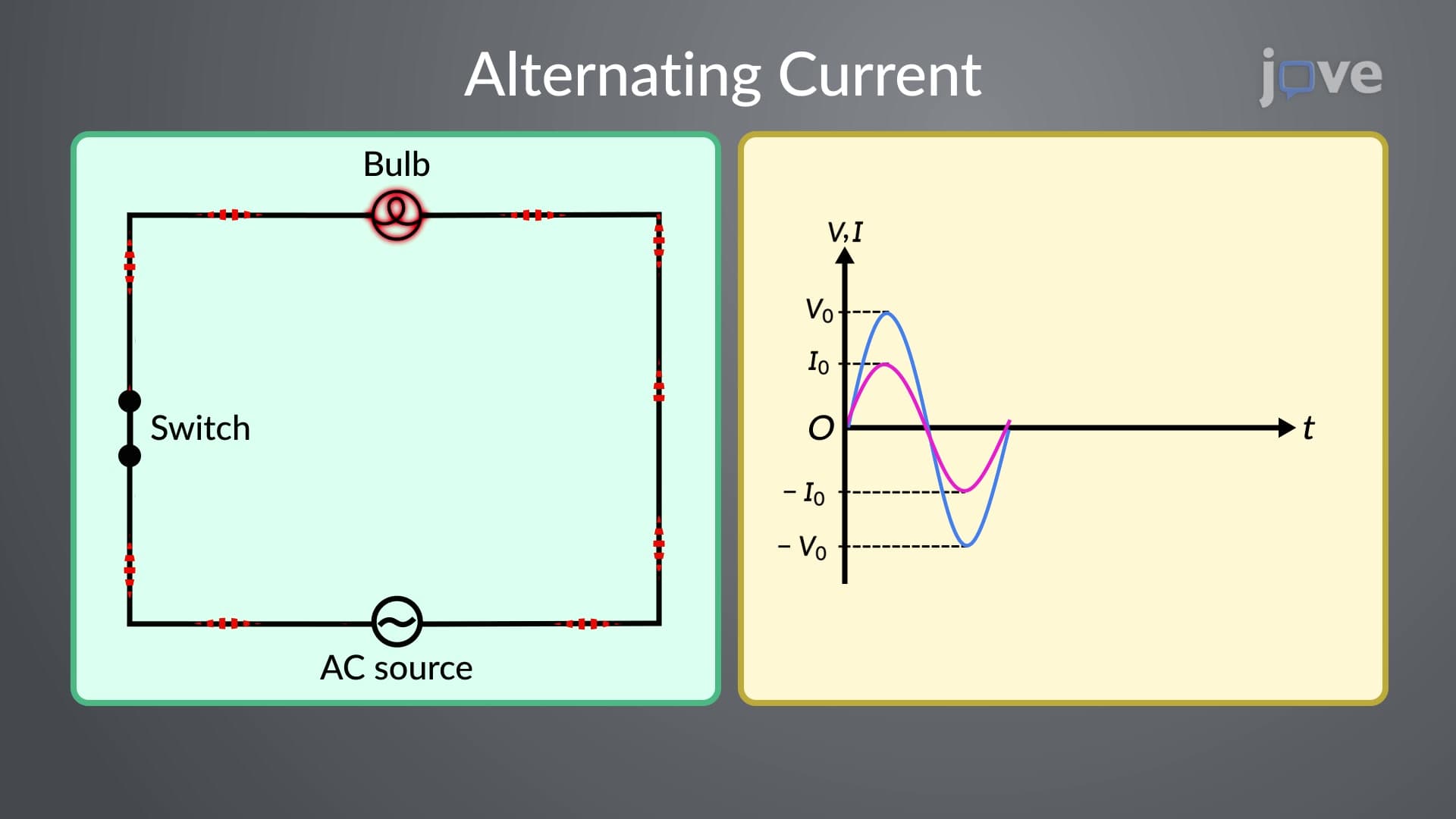
When analyzing a resistor in an AC circuit, the fundamental principle remains rooted in Ohm's law, but the sinusoidal nature of AC introduces new considerations. Unlike DC circuits where voltage and current are constant, AC circuits feature continuously varying voltage and current that follow sinusoidal patterns. The mathematical representation V(t) = V₀sin(ωt) describes how voltage varies with time, where V₀ represents the peak voltage and ω represents the angular frequency.
The most crucial characteristic of resistors in AC circuits is that voltage and current remain perfectly in phase. This means both reach their maximum and minimum values simultaneously-a property that distinguishes resistors from reactive components like capacitors and inductors. In practical terms, when analyzing household electrical systems or laboratory circuits, this in-phase relationship simplifies calculations significantly. Phasor diagrams provide a powerful visual tool for representing this relationship, where both voltage and current phasors point in the same direction and rotate together at angular frequency ω.
In real-world applications, resistive AC circuits appear everywhere from space heaters to incandescent light bulbs. Consider a typical American household where a 1500W space heater operates on 120V AC power-the heating element acts as a pure resistor, creating the in-phase relationship discussed. For students preparing for AP Physics or college-level electrical engineering courses, understanding this concept proves essential for analyzing more complex circuits involving RLC combinations.
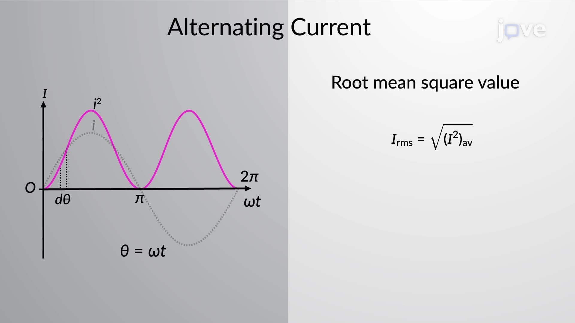
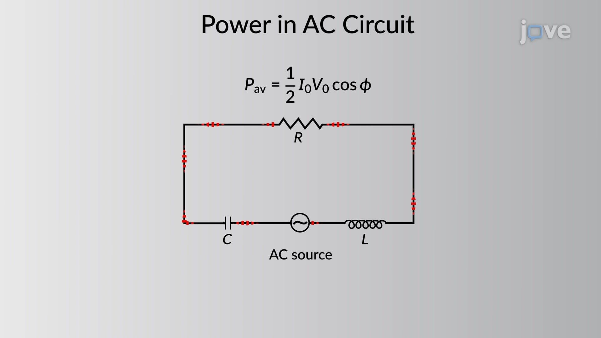
The instantaneous power in a resistive AC circuit follows P(t) = V(t) × I(t) = V₀I₀sin²(ωt), resulting in a time-varying power that's always positive. This mathematical relationship explains why resistors always dissipate energy as heat, never storing it. For standardized exams like the MCAT or AP Physics C, students frequently encounter problems requiring RMS (root-mean-square) calculations, where VRMS = V₀/√2 and IRMS = I₀/√2, making the average power calculation straightforward: P = VRMS × IRMS.
Related Micro-courses