Loading subject page…


8,255 views

Video Summary: Characteristics of Series Resonant Circuit Explained
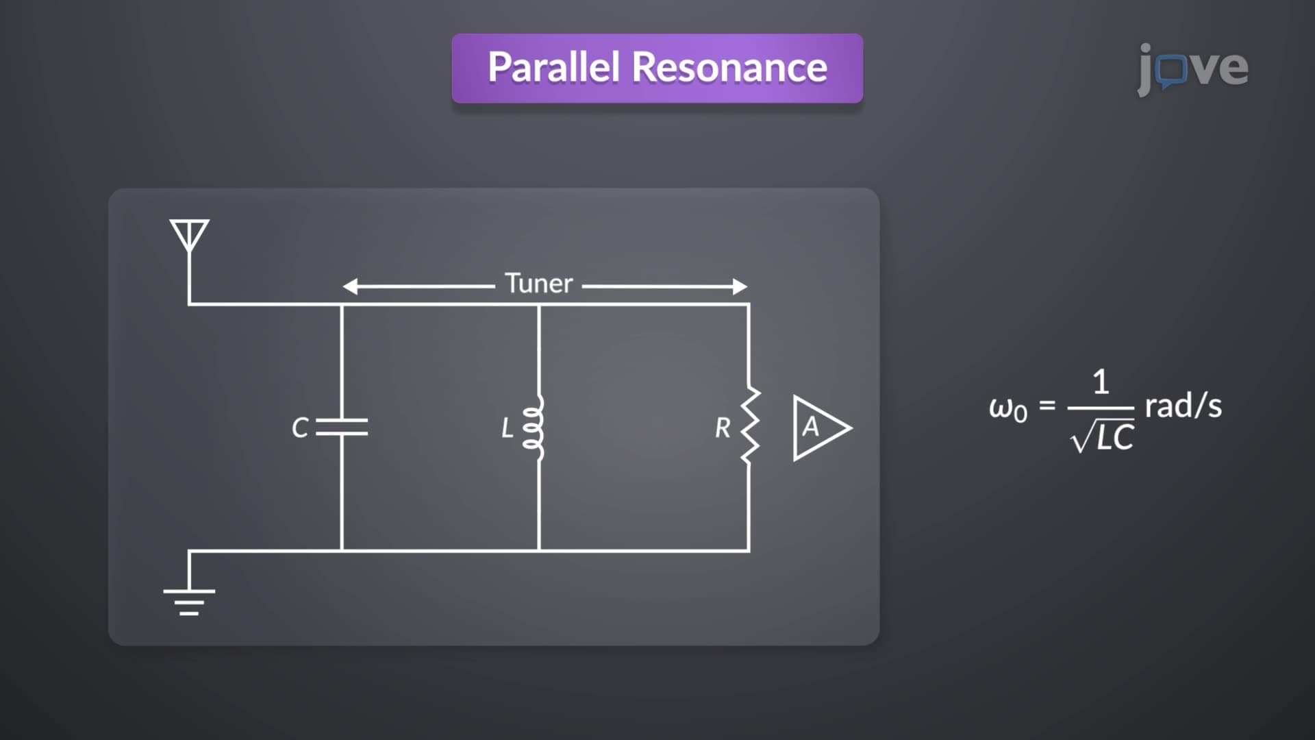
Did you know that every time you tune into a specific radio station, you're experiencing series resonance in action? Parallel resonance occurs when reactive components in a circuit create maximum impedance at a specific frequency, fundamentally different from the series resonance principles. Radio transmitters across the United States rely on precise frequency selection through resonant circuits to broadcast clear signals without interference. The characteristics of series resonant circuit explained here demonstrate how current peaks at resonance frequency while power dissipation reaches maximum values. Watch the full video on JoVE Coach to master this concept with expert-led visuals and step-by-step explanations.
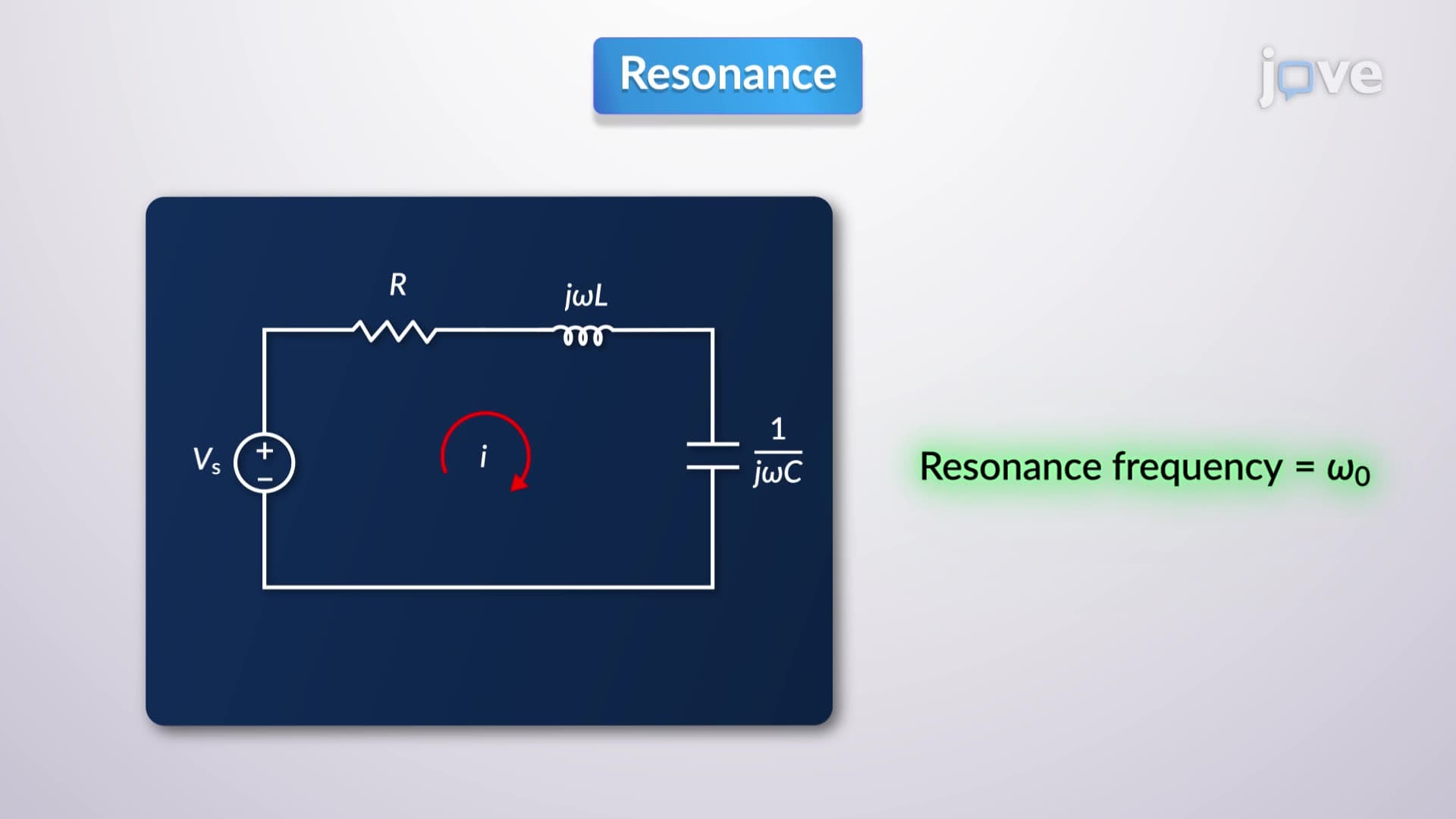
The characteristics of series resonant circuit explained through frequency analysis reveal fascinating electrical behavior that powers countless technologies around us. When an RLC series circuit reaches its resonant frequency, the inductive and capacitive reactances become equal in magnitude but opposite in phase, effectively canceling each other out. This phenomenon creates a unique condition where the circuit impedance reaches its minimum value, allowing maximum current flow.
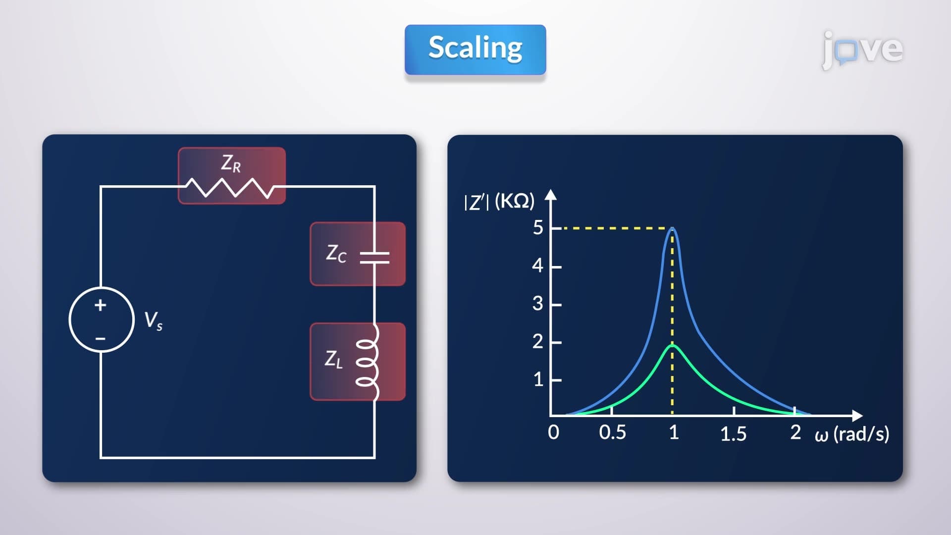
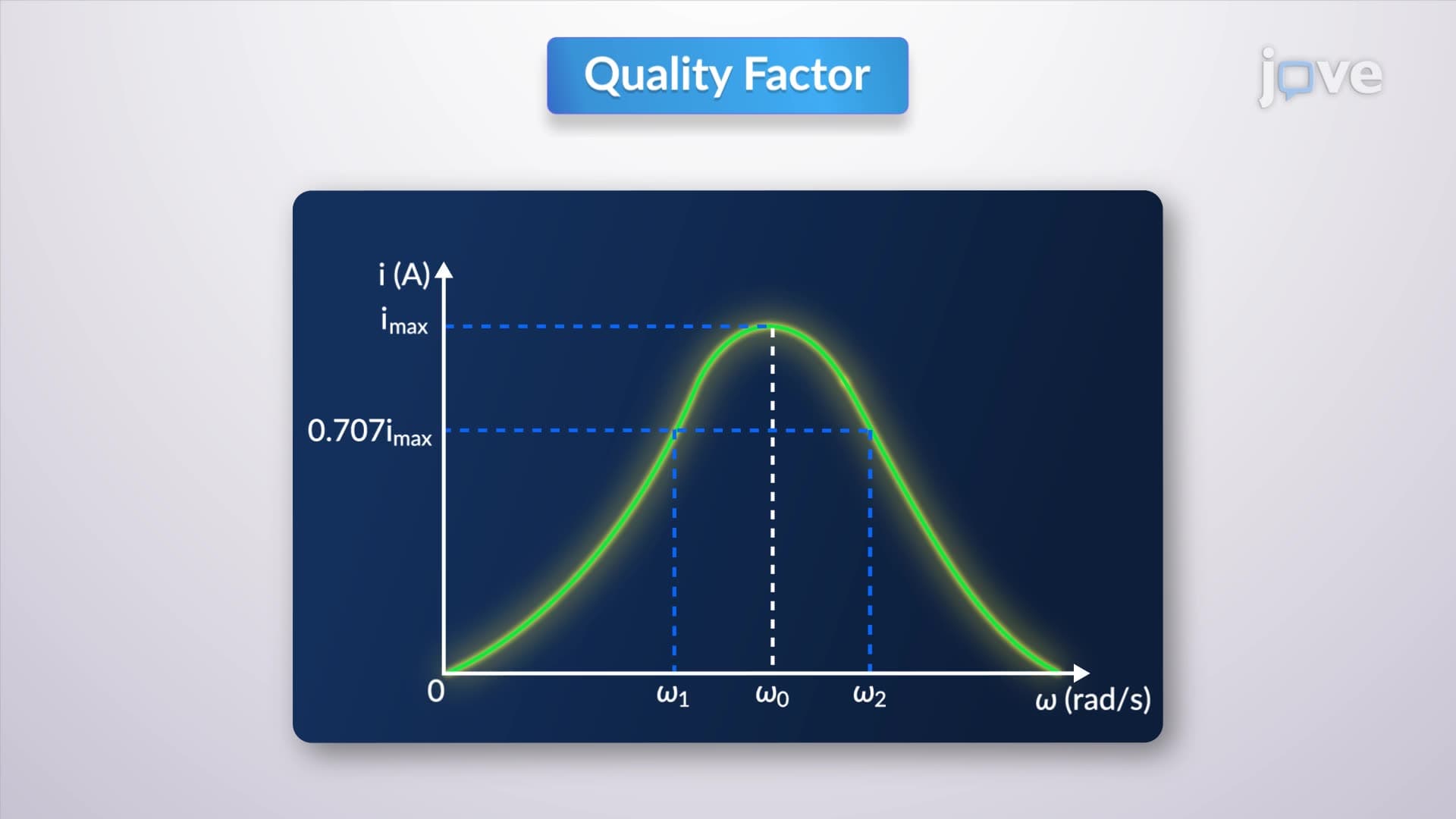
At the resonant frequency, current reaches its peak value because total circuit impedance equals only the resistance component. As frequency deviates from resonance, either increasing or decreasing, the current magnitude diminishes due to rising reactive impedance. The power dissipated in the circuit directly correlates with current squared, making power dissipation highest at resonance when current peaks.
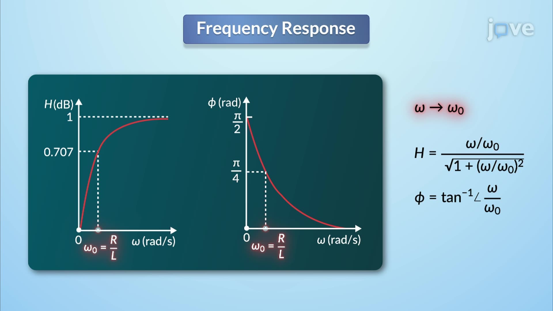
The half-power frequencies represent crucial reference points where current drops to 0.707 times its maximum value, corresponding to exactly half the maximum power dissipation. These frequencies define the circuit's bandwidth, calculated as the difference between upper and lower half-power frequencies. Students preparing for AP Physics exams frequently encounter problems requiring bandwidth calculations using the formula: BW = R/L, where resistance divided by inductance yields bandwidth in radians per second.
The quality factor (Q) quantifies how "sharp" or selective a resonant circuit behaves. Higher Q values indicate narrower bandwidths and greater frequency selectivity, essential for applications like radio receivers that must distinguish between closely spaced broadcast frequencies. Commercial FM radio stations in major US cities like New York and Los Angeles operate with precise frequency allocations, relying on high-Q circuits for clear signal separation.
Quality factor relates directly to energy storage efficiency, comparing maximum stored energy to energy dissipated per cycle. Engineers designing filters for telecommunications equipment across Silicon Valley companies like Apple and Google must carefully balance Q factors to achieve desired performance specifications.
Series resonant circuits find extensive applications in electronic systems throughout American industries. Radio transmitters use these circuits as band-pass filters, allowing specific frequencies to pass while attenuating others. Medical equipment manufacturers like General Electric and Medtronic incorporate resonant circuits in imaging systems and therapeutic devices.
College students studying electrical engineering at institutions like MIT and Stanford encounter series resonance concepts in circuits courses, typically during sophomore year. The mathematical relationships governing these circuits appear frequently on MCAT physics sections, particularly in questions involving electromagnetic phenomena and circuit analysis.
Related Micro-courses