Loading video…


 15 Concepts
 8.3K views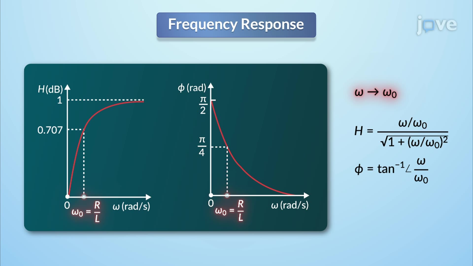

Video Summary: What Is Frequency Response Circuit
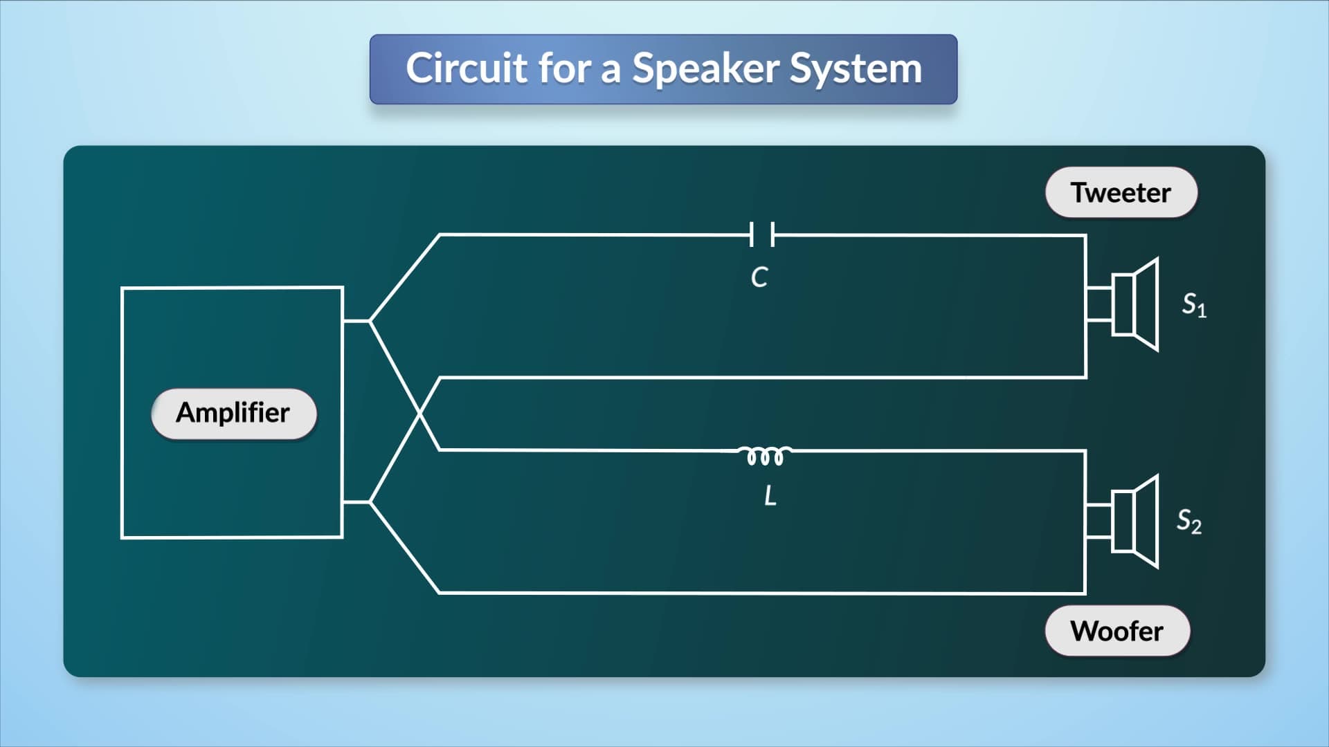
Ever wonder how your smartphone's audio equalizer boosts bass frequencies while leaving treble untouched? The secret lies in understanding gain and how circuits respond differently to various frequencies. A frequency response circuit, like those found in audio amplifiers used by companies such as Bose and Apple, demonstrates how gain varies with input frequency through inductive and resistive components. The circuit's transfer function reveals both magnitude and phase characteristics that determine signal processing behavior. Watch the full video on JoVE Coach to master this concept with expert-led visuals and step-by-step explanations.
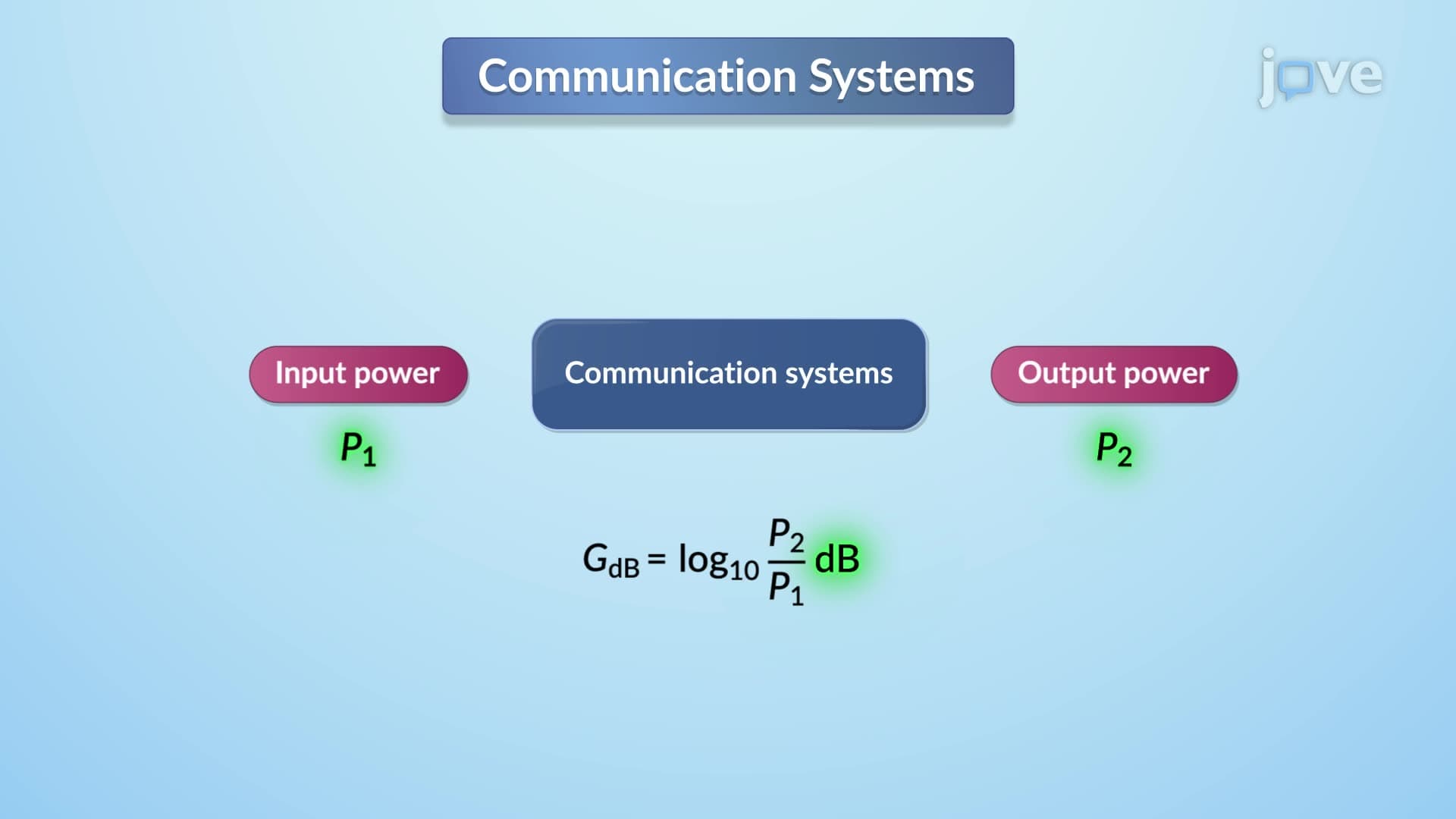
A frequency response circuit reveals how electrical systems process signals across different frequencies, making it essential for understanding modern electronics from smartphone amplifiers to medical diagnostic equipment. The concept centers on gain - the ratio of output signal strength to input signal strength - and how this ratio changes with frequency.
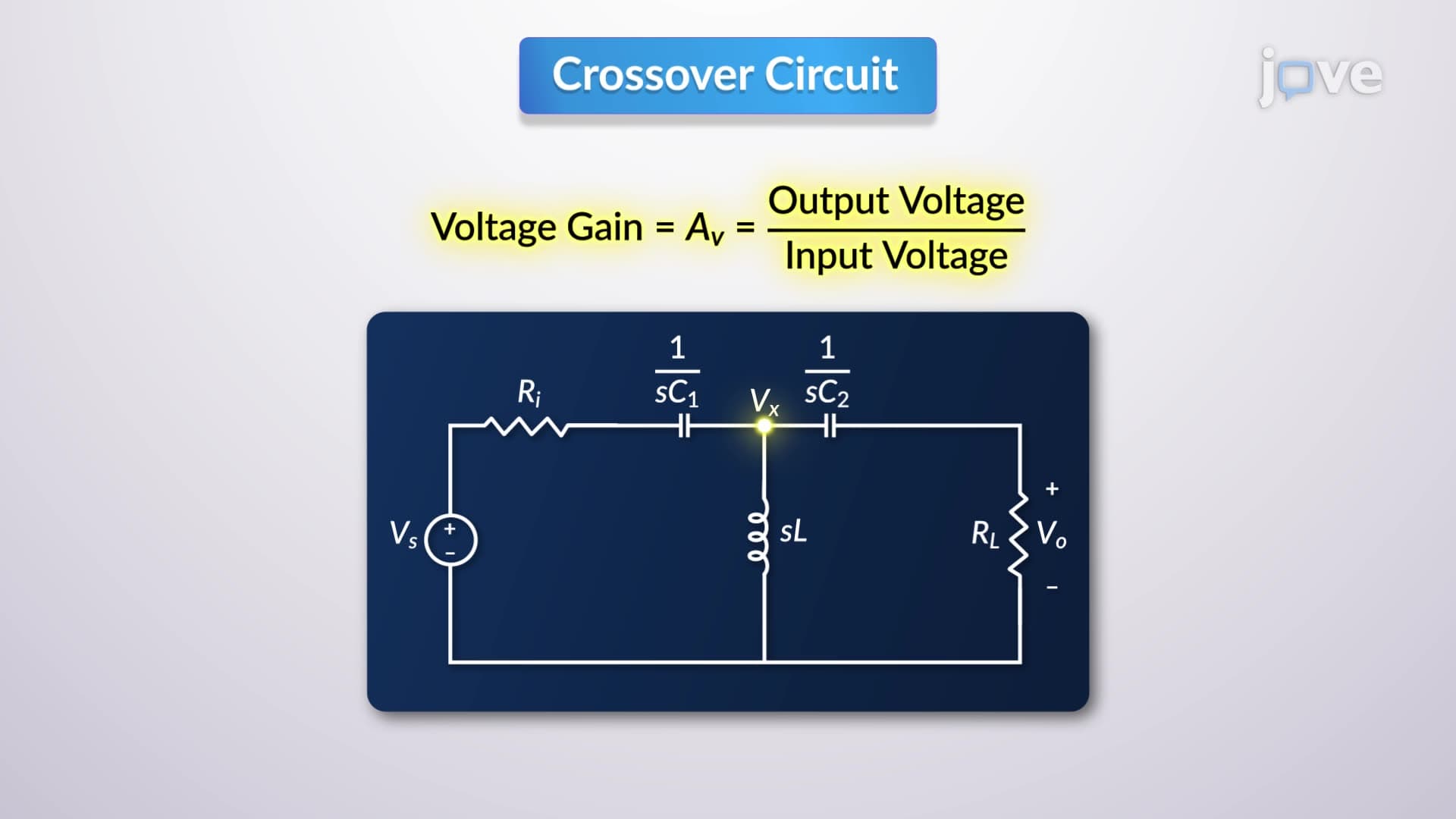
When analyzing inductive circuits, engineers transform time-domain representations into frequency-domain equivalents by replacing resistors and inductors with their corresponding impedances. This transformation simplifies complex calculations and reveals frequency-dependent behavior that's crucial for circuit design.
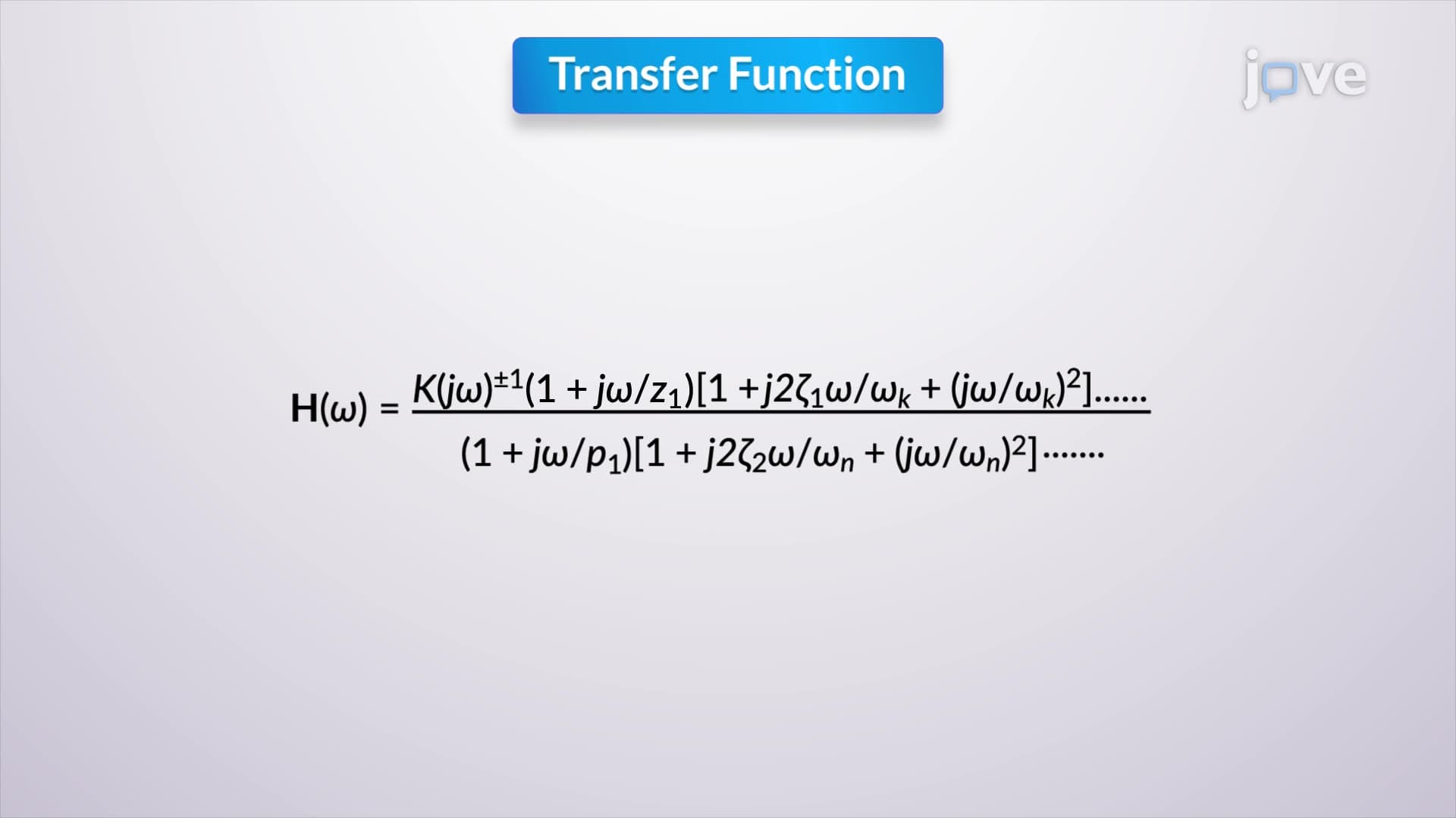
The transfer function H(jω) = Vout/Vin provides a mathematical framework for understanding circuit gain across frequencies. For an RL circuit, this function depends on the ratio L/R, which equals the circuit's time constant τ (tau). This relationship directly impacts gain definition in frequency-selective circuits.
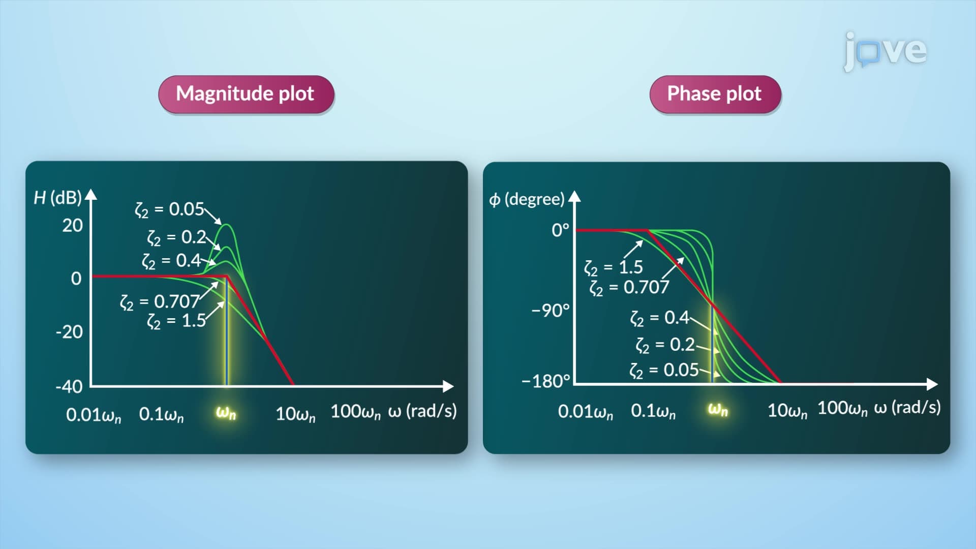
At low frequencies (approaching DC), inductive reactance becomes negligible, causing the transfer function to approach zero with a phase shift of π/2 radians (90 degrees). This behavior explains why inductors "block" DC current in practical applications like power supply filters used in computer motherboards.
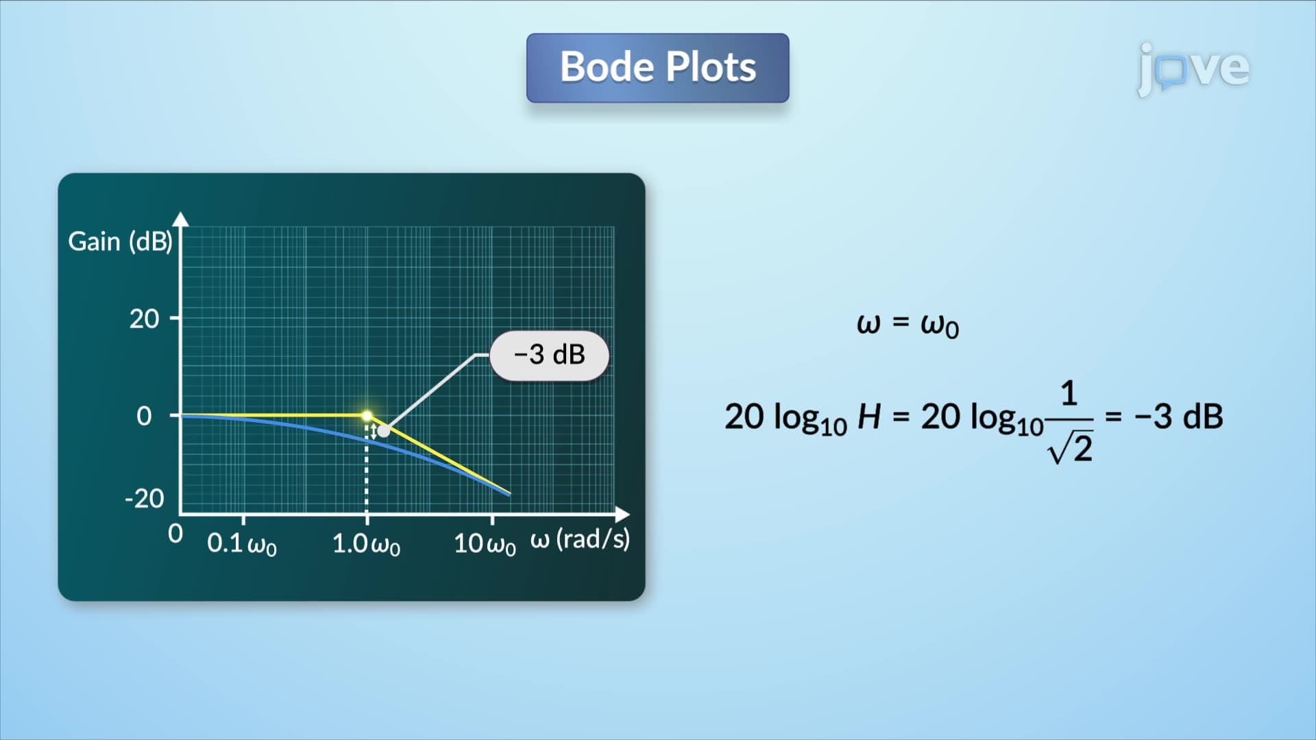
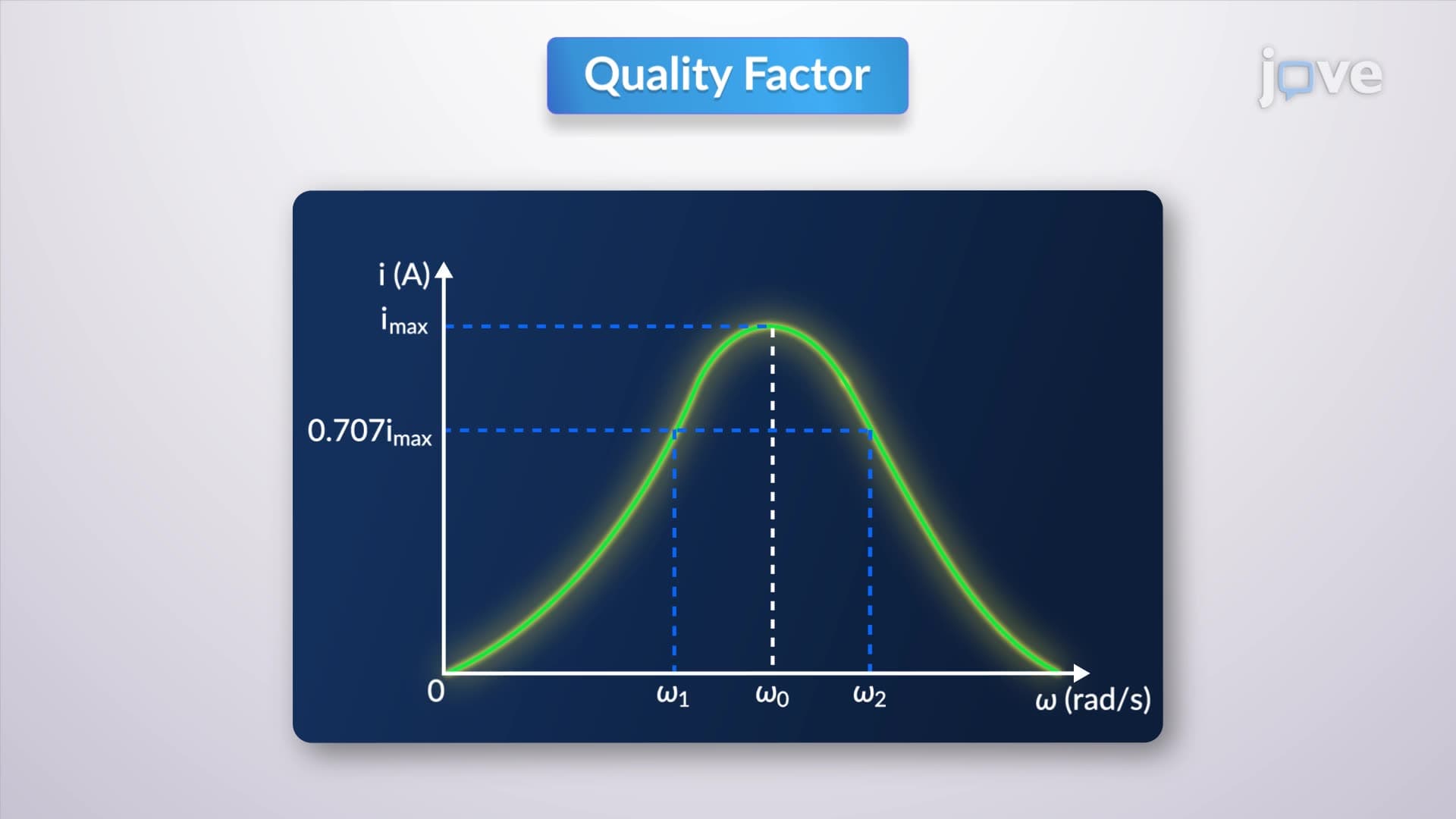
The cutoff frequency occurs when ω = 1/τ, where the amplitude reaches approximately 0.707 times its maximum value and phase shift equals π/4 radians (45 degrees). This -3dB point is fundamental in filter design and appears frequently on AP Physics exams and college-level Electrical Engineering coursework.
At high frequencies, inductive reactance dominates, causing the transfer function to approach unity (gain = 1) with zero phase shift. This characteristic makes RL circuits effective as high-pass filters in audio systems, allowing treble frequencies to pass while attenuating bass frequencies.
Understanding what is gain in detail becomes crucial when students encounter these concepts in standardized tests like the MCAT Physics section or engineering licensing exams. The frequency response demonstrates how gain isn't constant but varies predictably with input frequency, forming the foundation for advanced topics in signal processing and communications systems taught at institutions like MIT, Stanford, and Georgia Tech.
Related Micro-courses