Loading video…


 15 Concepts
 8.3K views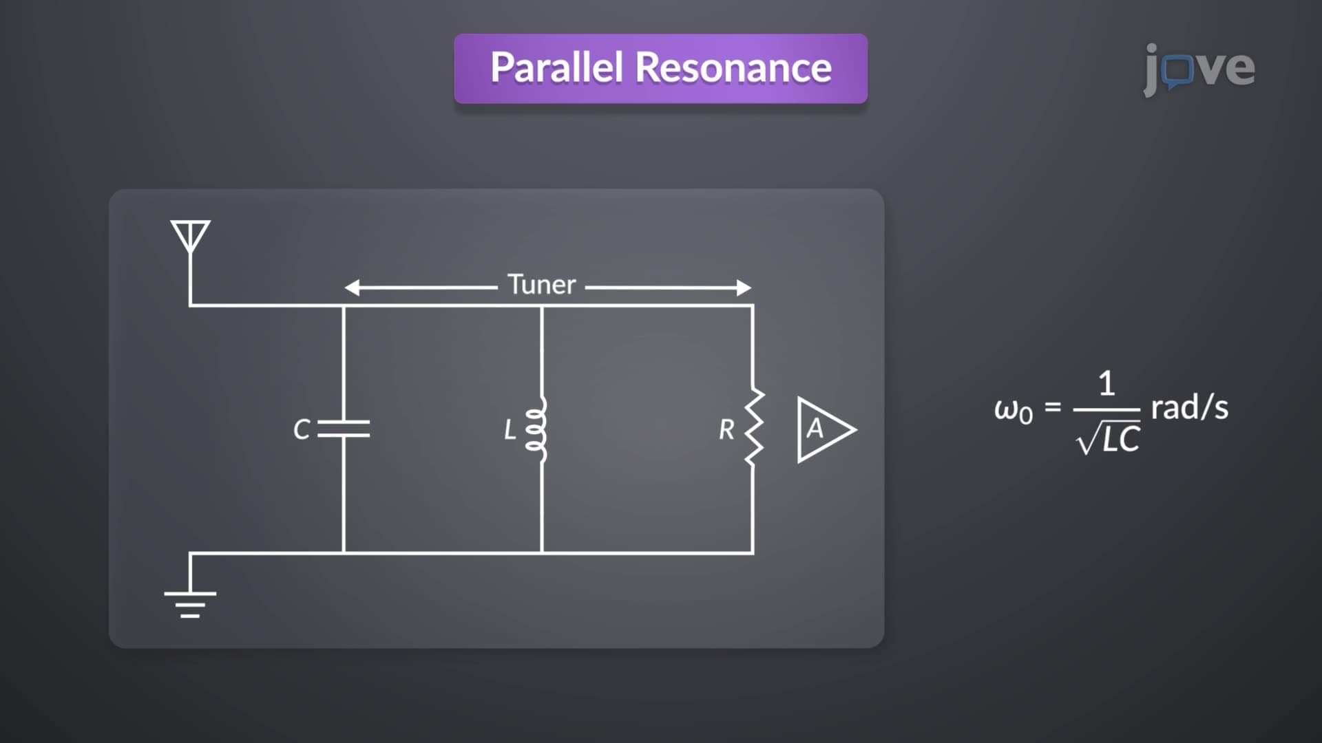

Video Summary: What Is Parallel Resonance
Ever wonder how your car radio instantly locks onto your favorite FM station among hundreds of broadcasting frequencies? The frequency response of op amp circuits and parallel resonance work together in radio tuners across America, from New York's Z100 to Los Angeles' KIIS-FM, enabling precise frequency selection. What is parallel resonance reveals how inductors and capacitors create an electrical "sweet spot" where energy oscillates efficiently between magnetic and electric fields, minimizing current draw while maximizing signal clarity. Watch the full video on JoVE Coach to master this concept with expert-led visuals and step-by-step explanations.
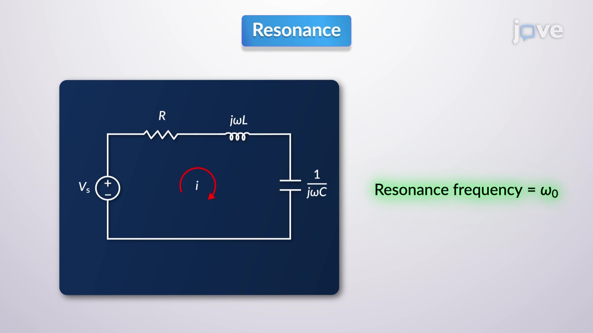
What is parallel resonance represents a fundamental phenomenon in AC circuit analysis where a resistor, inductor, and capacitor connected in parallel create a unique frequency-dependent behavior. Unlike series resonance where current reaches maximum, parallel resonance produces minimum current at the resonant frequency. This occurs because the inductive and capacitive reactances become equal in magnitude but opposite in phase, effectively canceling each other out.
The mathematics behind parallel resonance centers on admittance rather than impedance. At resonance, the imaginary component of total admittance equals zero, leaving only the resistive component. This condition defines the resonant frequency as f₀ = 1/(2π√LC), identical to series resonance but with dramatically different current characteristics.
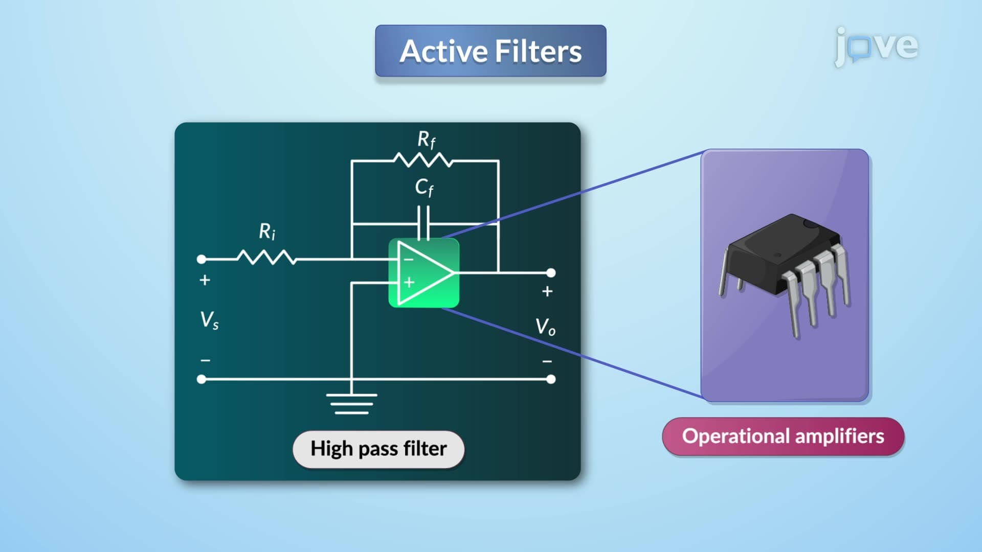
The frequency response of op amp circuits often incorporates parallel resonant elements for filtering and frequency selection. In operational amplifier applications, parallel resonant circuits create notch filters that reject specific frequencies while passing others. This principle appears extensively in active filter designs taught in universities like MIT and Stanford.
Students preparing for AP Physics or college-level electrical engineering courses encounter this concept when analyzing how frequency response of op amp circuits tutorial problems demonstrate bandwidth calculations. The current versus frequency plot shows a characteristic dip at resonance, contrasting sharply with the peak observed in series resonant circuits.
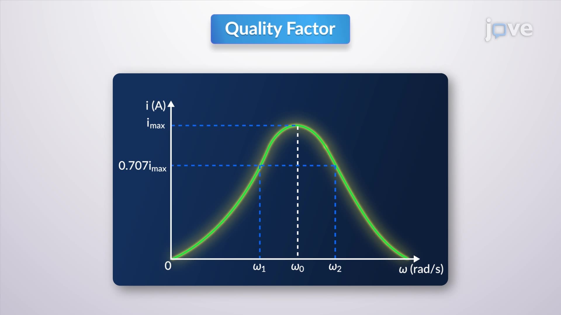
Quality factor (Q) quantifies the sharpness of the resonant response, directly impacting bandwidth in practical applications. Higher Q values produce narrower bandwidths and more selective frequency responses, crucial for applications like radio receivers used by stations such as NPR affiliates nationwide.
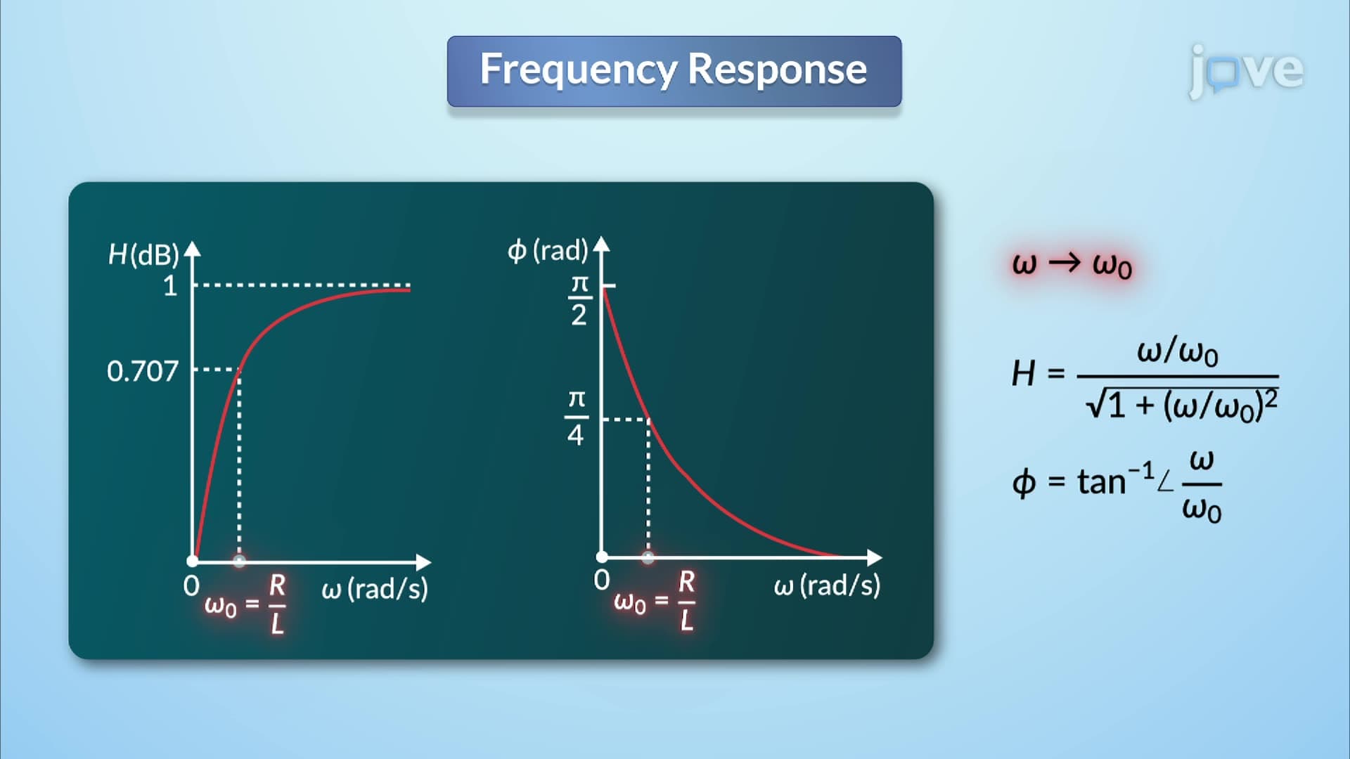
The half-power frequencies, where current reaches 1.414 times the minimum resonant current, define the circuit's bandwidth as BW = f₂ - f₁. This relationship proves essential for MCAT physics sections and engineering coursework, where students must calculate filter performance specifications.
American broadcasting systems rely heavily on parallel resonant circuits for channel separation and signal processing. From smartphone RF front-ends to satellite communication systems, understanding frequency response of op amp circuits concept enables engineers to design selective amplifiers and filters that isolate desired signals from interference.
Related Micro-courses