Loading video…


 18 Concepts
 6.9K views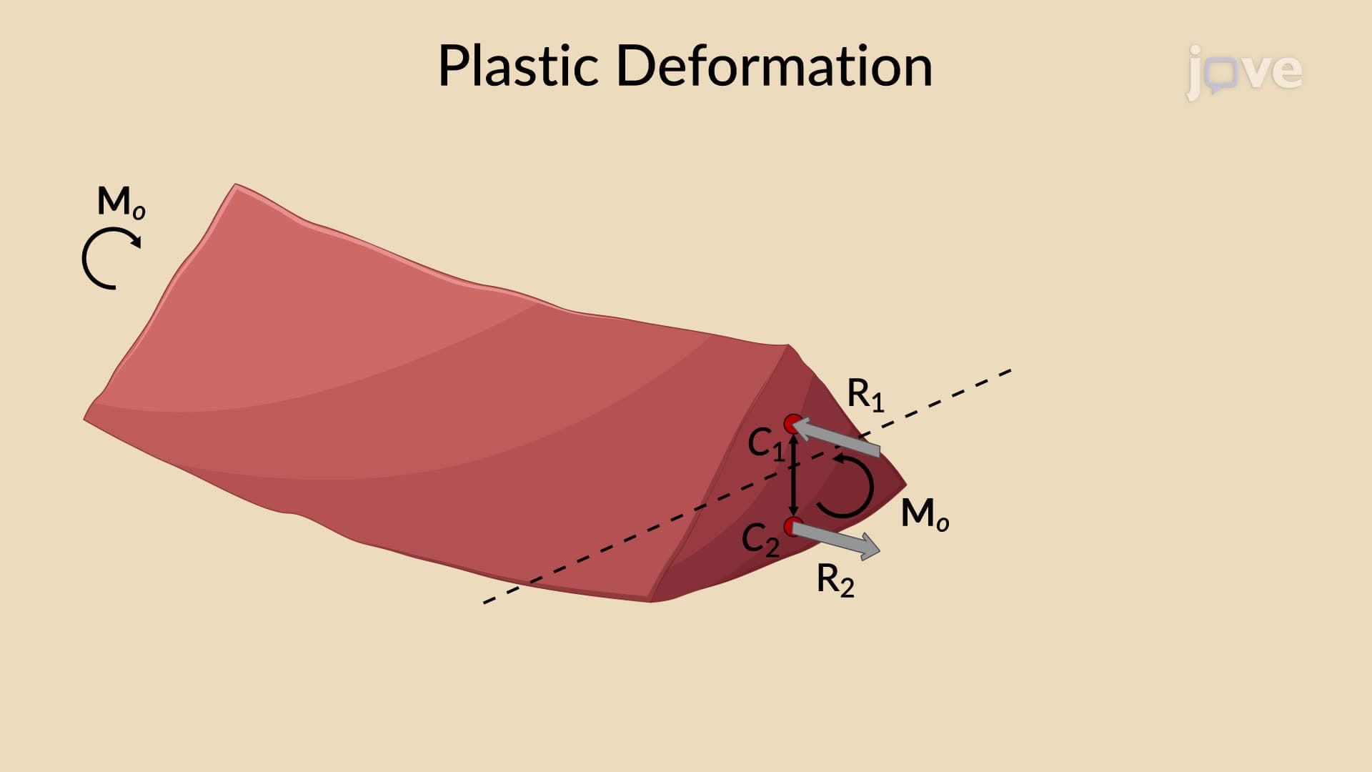

Video Summary: What Is Plastic Deformations of Members
Ever wonder why a steel beam in a skyscraper like New York's One World Trade Center can bend but not break under extreme loads? Plastic deformations of members occur when structural elements undergo permanent shape changes beyond their elastic limit, with stress distributions that create unique neutral axis positions. Unlike elastic deformation, the neutral axis no longer coincides with the member's centroid, fundamentally changing how engineers calculate load-bearing capacity. Watch the full video on JoVE Coach to master this concept with expert-led visuals and step-by-step explanations.
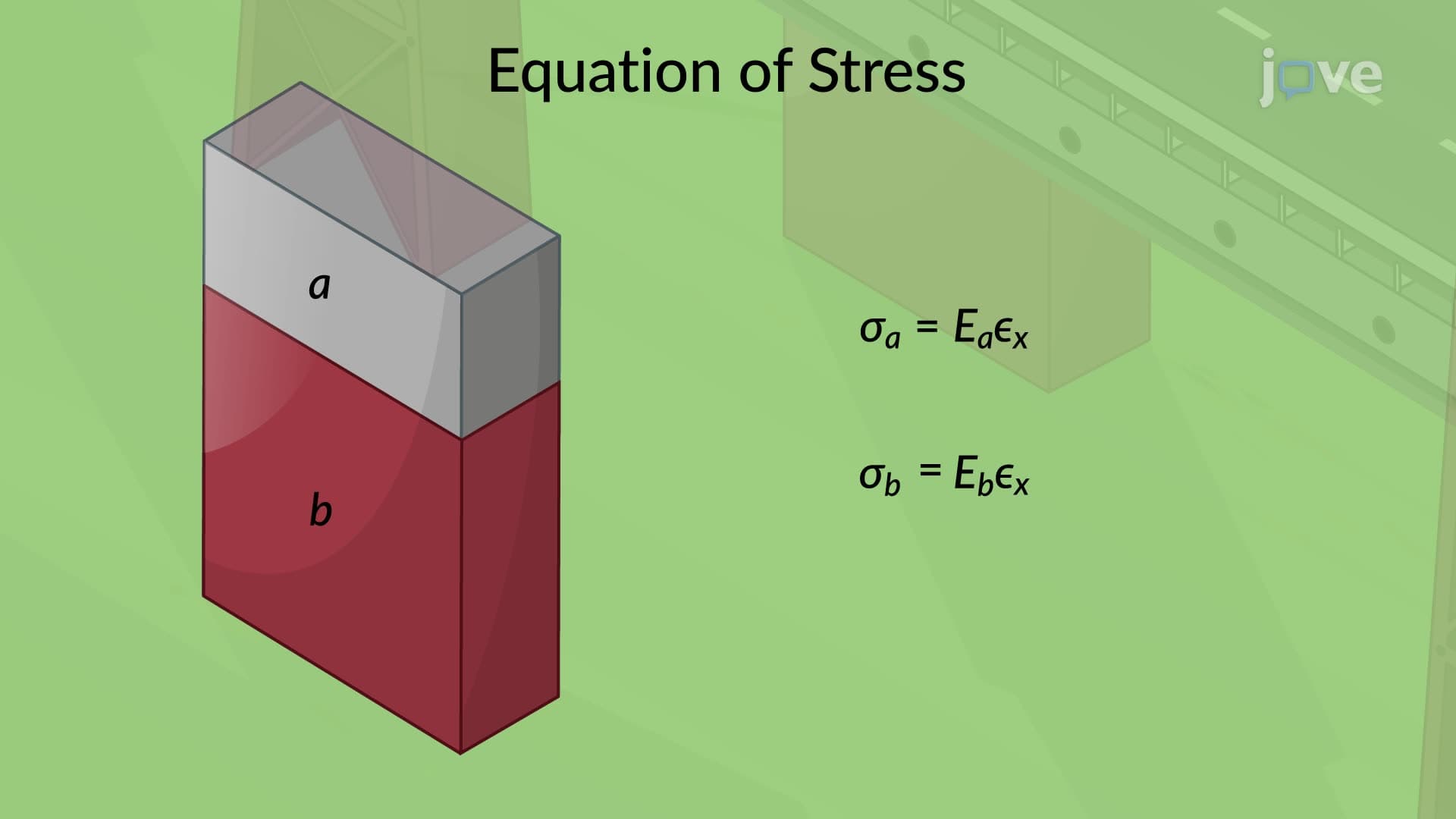
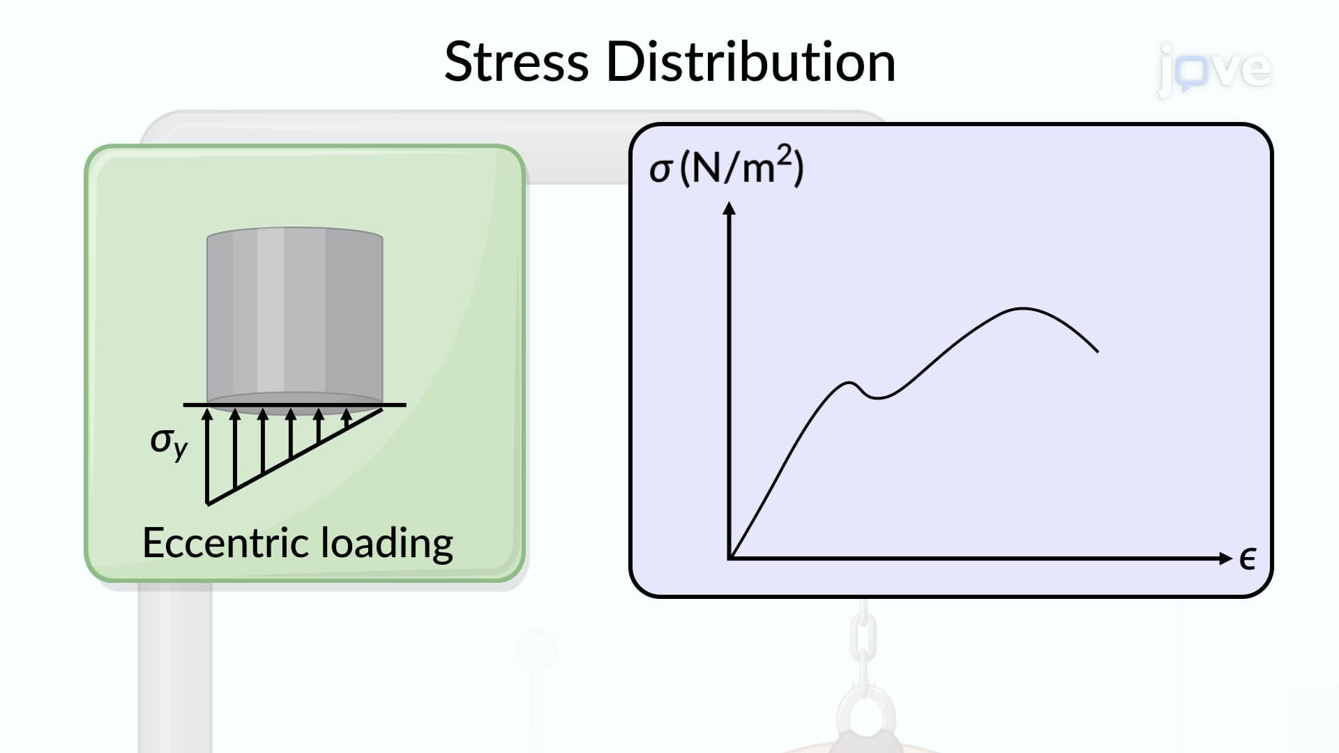
Plastic deformations of members represent a critical transition point in structural behavior where materials undergo permanent shape changes that cannot be reversed upon load removal. Unlike elastic deformation, where stress and strain maintain a linear relationship following Hooke's Law, plastic deformation occurs when applied stresses exceed the material's yield strength. This phenomenon is particularly important in structural steel design, where engineers must account for both serviceability limits (elastic behavior) and ultimate strength limits (plastic behavior).
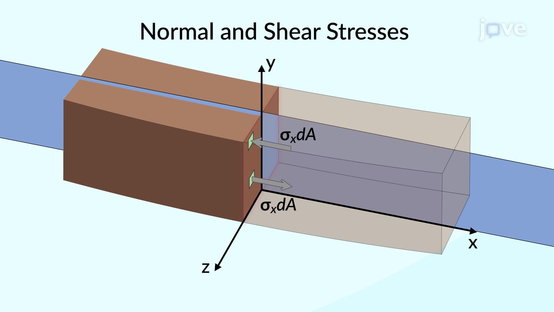
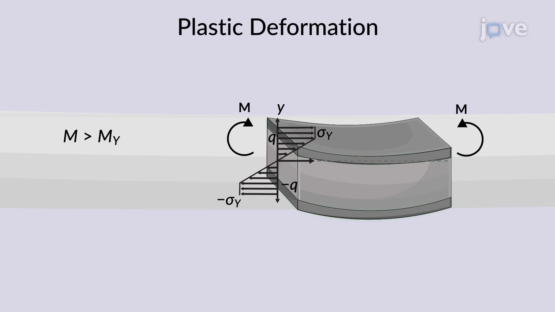
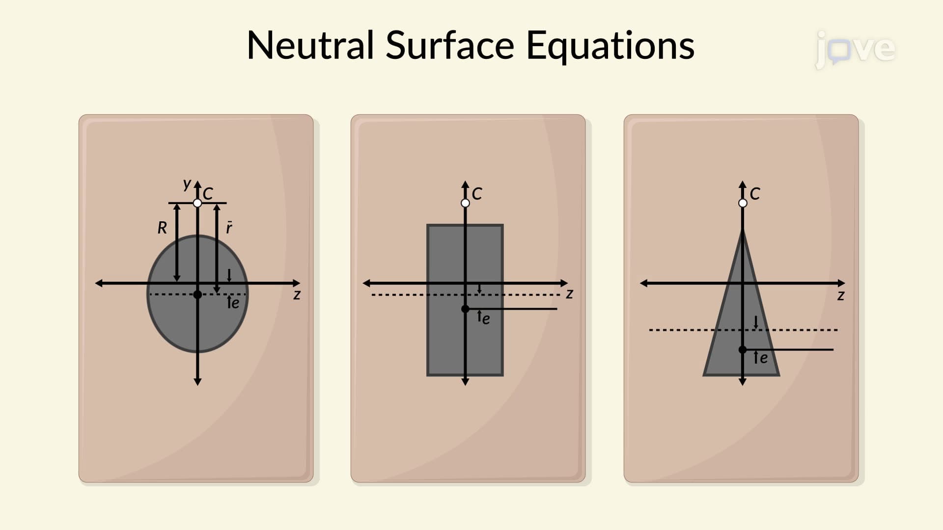
The most significant characteristic distinguishing plastic from elastic behavior is the fundamental shift in neutral axis location. In elastic bending, the neutral axis coincides with the centroidal axis of the cross-section, maintaining a linear stress distribution. However, during plastic deformation, stresses become uniformly distributed above and below the neutral axis, creating rectangular stress blocks rather than triangular distributions. This uniform stress pattern, typically equal to the material's yield strength, forces the neutral axis to relocate to a position where it divides the cross-section into two equal areas.
The mechanics of plastic deformation involve equilibrium between compressive forces above the neutral axis (R1) and tensile forces below it (R2). These resultant forces form a couple system equivalent to the applied bending moment. The plastic moment capacity, denoted as Mp, equals half the product of the total cross-sectional area, the yield stress magnitude, and the distance (d) between the centroids of the two equal areas created by the neutral axis division. This relationship, Mp = (A × σy × d)/2, provides engineers with a straightforward method for calculating ultimate moment capacity.
Understanding plastic deformations proves essential for structural engineers working with the American Institute of Steel Construction (AISC) specifications and building codes. The concept directly applies to plastic design methods used in high-rise construction, bridge design, and seismic engineering applications. For students preparing for the Fundamentals of Engineering (FE) exam or pursuing structural engineering licenses, mastering plastic analysis techniques is crucial for understanding load and resistance factor design (LRFD) principles commonly employed in US practice.
Related Micro-courses