Loading subject page…

- Physics
- Alternating Current Circuits
- RLC Series Circuits: Impedance
Micro-course: Alternating-Current Circuits
29,600 views
Learn key concepts and earn your certificate.

RLC Series Circuits: Impedance

00:00
01:29
Video Summary: What Is Rlc Series Circuits Impedance
Ever wondered why your smartphone charger gets warm or why power lines hum at 60 Hz? The answer lies in RLC series circuits impedance, the total opposition to alternating current flow in circuits containing resistors, inductors, and capacitors. From the electrical grid powering Tesla's Supercharger stations to the tuning circuits in FM radios, impedance determines how AC circuits behave in real-world applications. This fundamental concept combines resistance with reactive components using phasor analysis and the Pythagorean theorem. Watch the full video on JoVE Coach to master this concept with expert-led visuals and step-by-step explanations.
- Understand what is RLC series circuits impedance and how it differs from simple resistance in DC circuits
- Identify the three components (resistance, inductive reactance, and capacitive reactance) that contribute to total impedance
- Apply the Pythagorean theorem to calculate impedance magnitude using Z = √(R² + (XL - XC)²)
- Analyze phase relationships between voltage and current in RLC circuits using phasor diagrams
- Evaluate how frequency affects inductive and capacitive reactances in series circuits
- Calculate phase angles using the relationship φ = arctan((XL - XC)/R)
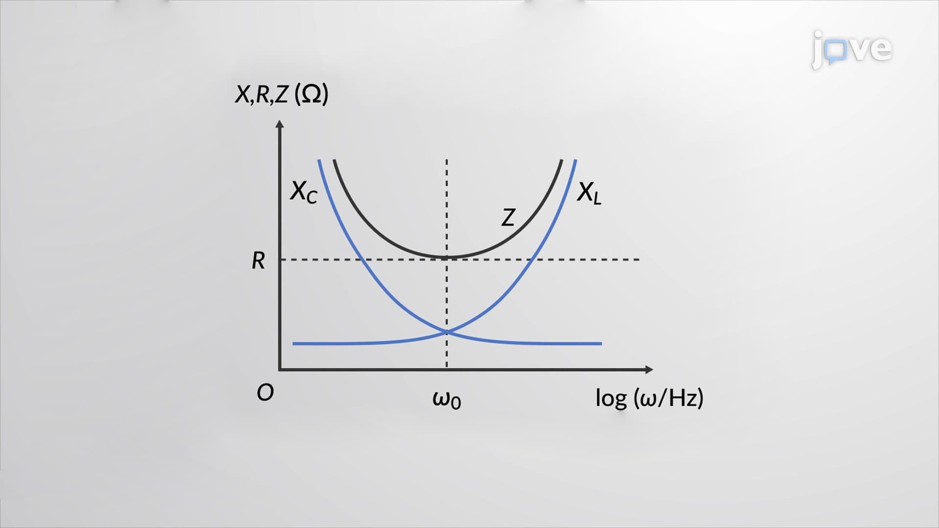
- Compare impedance behavior at different frequencies, including resonance conditions
- Recognize real-world applications in power systems, audio equipment, and electronic filters
Understanding RLC Series Circuits Impedance Fundamentals
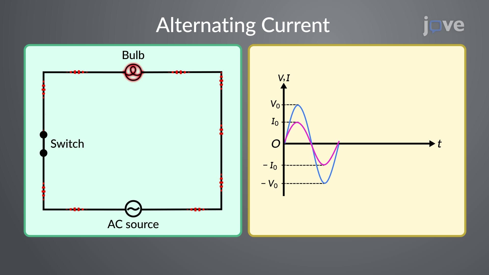
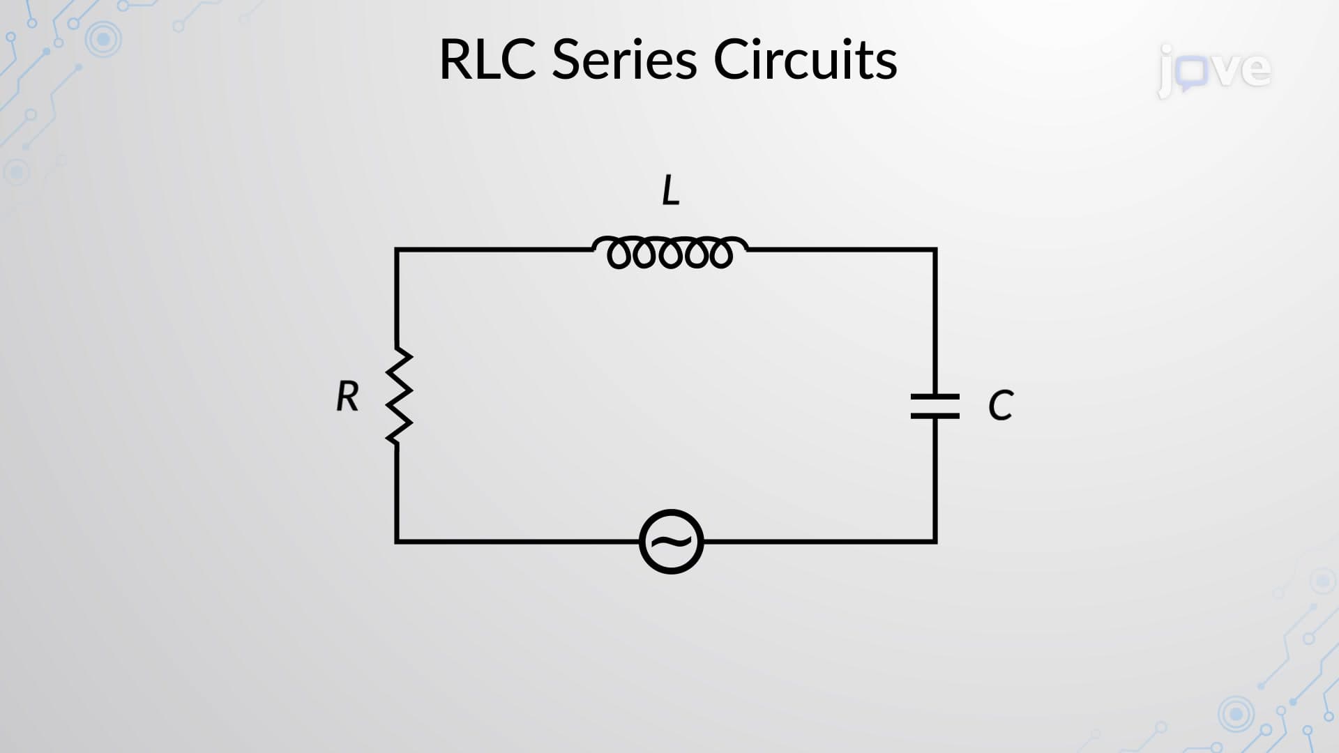
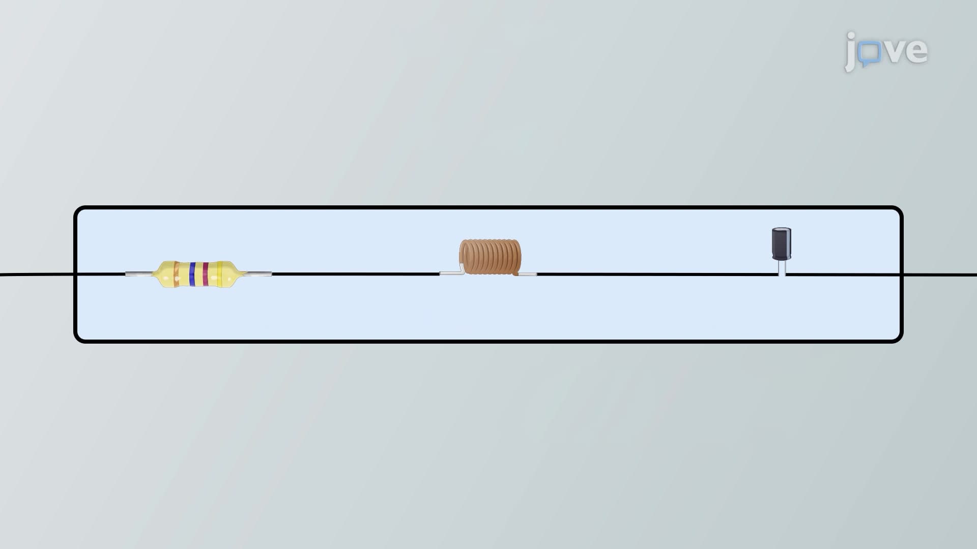
RLC series circuits impedance represents the total opposition to alternating current flow when a resistor (R), inductor (L), and capacitor (C) are connected in series. Unlike DC circuits where only resistance matters, AC circuits must account for reactive components that cause voltage and current to be out of phase.
The impedance concept becomes critical when analyzing power distribution systems across the United States. For instance, utility companies must consider impedance when designing transmission lines from power plants to cities like Los Angeles or New York, where reactive components affect power efficiency and voltage regulation.
Mathematical Foundation and Phasor Analysis
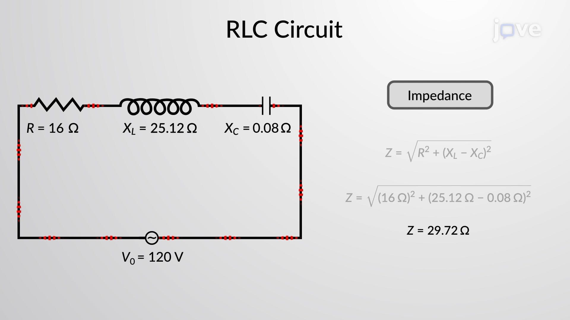
The impedance magnitude follows the relationship: Z = √(R² + (XL - XC)²), where XL represents inductive reactance and XC represents capacitive reactance. This formula emerges from phasor analysis, treating AC quantities as rotating vectors in the complex plane.
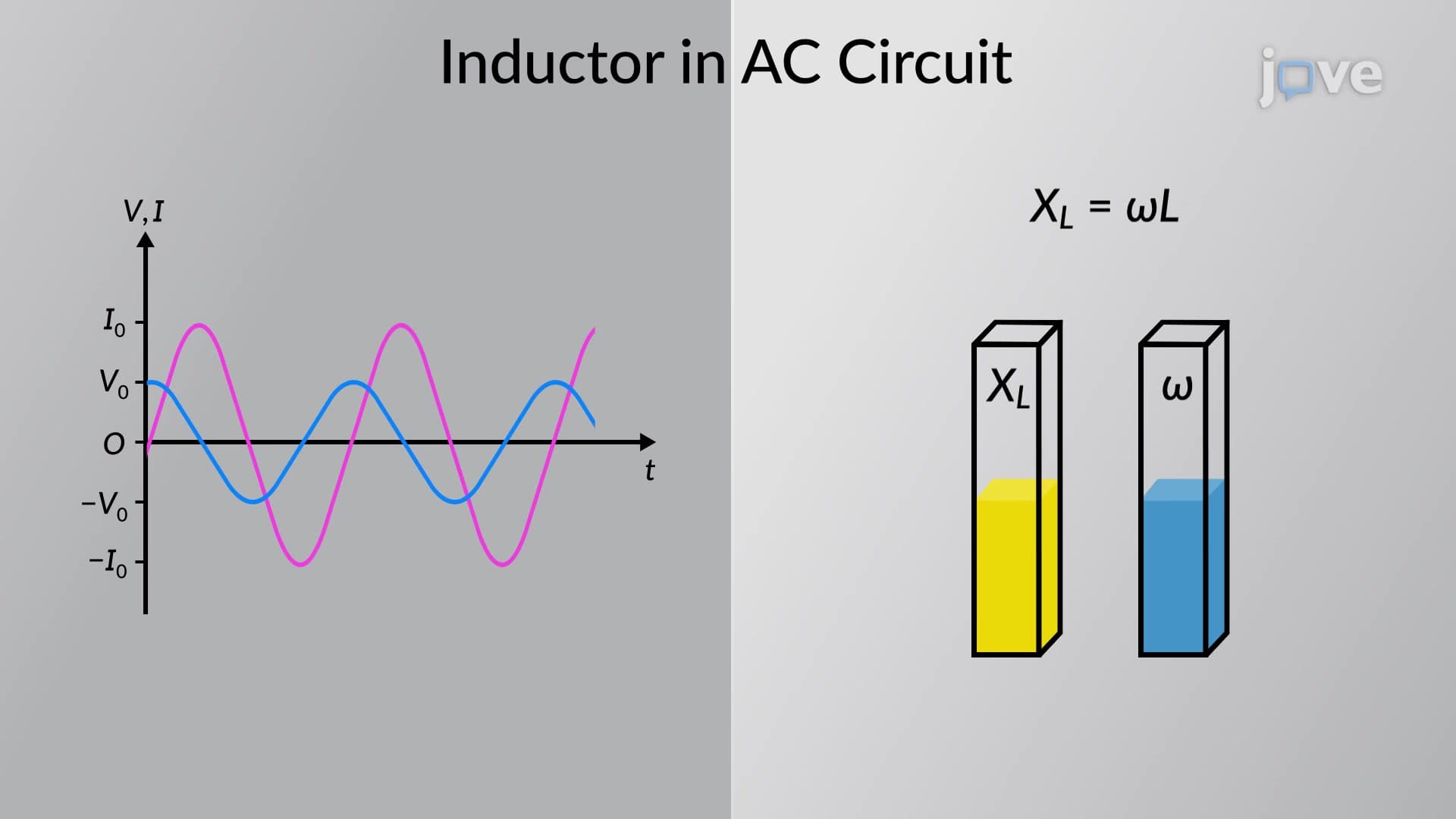
Inductive reactance increases with frequency: XL = 2πfL, while capacitive reactance decreases: XC = 1/(2πfC). At 60 Hz (standard US power frequency), a 200 microhenry inductor produces XL = 0.075 ohms, while a 100 microfarad capacitor yields XC = 26.5 ohms.
Phase Relationships and Practical Implications
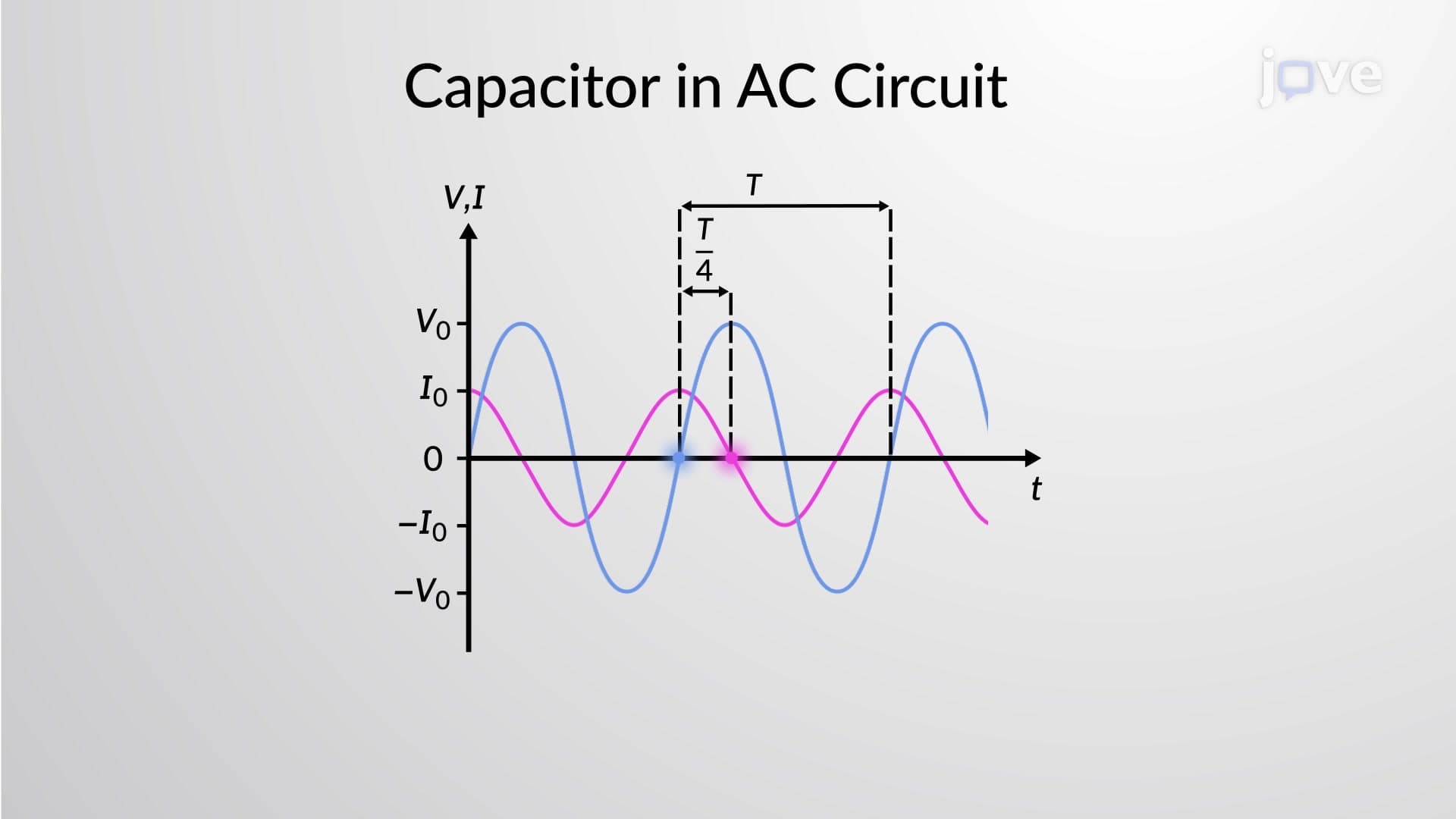
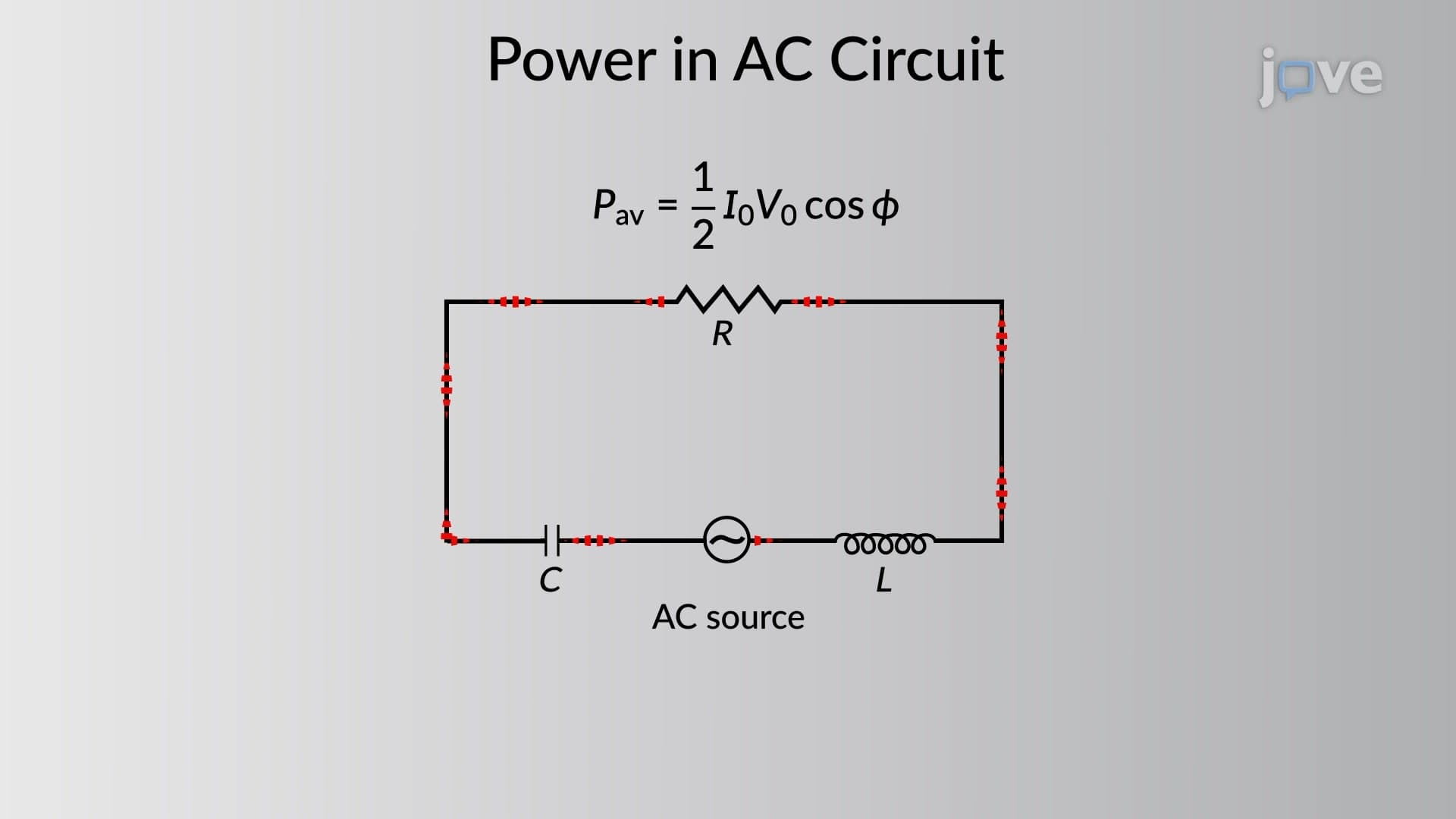
The phase angle between voltage and current is: φ = arctan((XL - XC)/R). When XL > XC, the circuit appears inductive with current lagging voltage. When XC > XL, the circuit appears capacitive with current leading voltage. This phase relationship directly impacts power factor in industrial applications.
Applications in US Educational Systems and Beyond
Students encounter RLC impedance concepts in AP Physics C courses, college electrical engineering programs, and professional licensing exams. MIT's introductory physics curriculum emphasizes impedance analysis for understanding everything from audio amplifiers to MRI machine design. The concept appears frequently on MCAT physics sections, particularly in questions about medical device functionality.
Real-world applications span from smartphone wireless charging circuits to the massive impedance matching networks in AM radio transmitters across the American Midwest. Understanding impedance helps explain why electrical engineers at companies like General Electric must carefully design power factor correction systems for manufacturing plants.
Frequently Asked Questions
RLC series circuits impedance is the total opposition to AC current flow in a circuit containing a resistor, inductor, and capacitor connected in series. It combines resistance (which opposes current) with reactances (which cause phase shifts between voltage and current). Unlike DC resistance, impedance varies with frequency and includes both magnitude and phase components.
AP Physics C frequently tests impedance calculations using the formula Z = √(R² + (XL - XC)²) and phase angle relationships. Students must demonstrate understanding of how frequency affects reactances, calculate impedance at specific frequencies, and interpret phasor diagrams. Free response questions often combine impedance with power calculations and resonance conditions.
College exams typically require students to analyze complex multi-frequency scenarios and connect impedance to power factor concepts. Students must master both mathematical calculations and conceptual understanding of how reactive components affect circuit behavior. The key is practicing frequency-dependent problems and understanding when circuits become capacitive versus inductive.
Power companies like Pacific Gas & Electric use impedance analysis to design efficient transmission networks and prevent voltage drops. Impedance matching ensures maximum power transfer, while impedance calculations help predict system stability during load changes. Understanding impedance also helps engineers design power factor correction systems that reduce energy costs for industrial customers.
Not at all! While the mathematics involves some trigonometry, the core concepts build naturally on Ohm's law and basic AC principles. High school students already understand resistance, so adding reactances as frequency-dependent oppositions makes intuitive sense. Starting with simple numerical examples helps students grasp the concepts before tackling complex calculations.
Focus on memorizing key formulas (Z = √(R² + (XL - XC)²), XL = 2πfL, XC = 1/(2πfC)) and practice frequency-dependent calculations. Work through problems involving power factor, resonance conditions, and impedance matching. Many state licensing boards test practical applications, so understand how impedance affects real power systems and motor circuits.
RLC impedance forms the foundation for filter design, amplifier analysis, and signal processing concepts in advanced coursework. Students who master impedance concepts excel in courses covering operational amplifiers, digital signal processing, and RF circuit design. The mathematical tools and phasor analysis techniques apply directly to advanced topics like transmission line theory and antenna design.
Progress to parallel RLC circuits, then explore resonance phenomena and quality factor calculations. Advanced topics include transmission line impedance, Smith charts for RF applications, and three-phase power system analysis. These concepts appear in upper-level electrical engineering courses and professional power systems analysis.
Related Micro-courses

14 Concepts

14 Concepts

15 Concepts