Loading subject page…

- Physics
- Direct Current Circuits
- Combination Of Resistors
Micro-course: Direct-Current Circuits
52,445 views
Learn key concepts and earn your certificate.


Combination Of Resistors


00:00
01:18
Video Summary: What are Combination of Resistors
Ever wondered how your smartphone manages to power dozens of components simultaneously without burning out? The secret lies in the combination of resistors that control current flow throughout the device. From the simple flashlight circuits used in high school physics labs across American classrooms to the complex electronic systems in Tesla vehicles, understanding how resistors work together in series and parallel configurations is fundamental to electrical engineering. This concept demonstrates how to calculate total resistance, current distribution, and voltage drops when multiple resistors are connected in various arrangements. Watch the full video on JoVE Coach to master this concept with expert-led visuals and step-by-step explanations.
- Understand what are combination of resistors and distinguish between series, parallel, and mixed circuit configurations
- Identify equivalent resistance values for different resistor arrangements using appropriate mathematical formulas
- Analyze current flow patterns and voltage distribution across individual components in complex circuits
- Apply Ohm's law systematically to solve for unknown quantities in combination circuits
- Evaluate the advantages and disadvantages of series versus parallel resistor connections in practical applications
- Compare how current divides in parallel branches versus remaining constant in series connections
- Recognize real-world applications of resistor combinations in household electronics and automotive systems
- Explore problem-solving strategies for mixed circuits containing both series and parallel elements
Understanding What are Combination of Resistors
Combination of resistors refers to electrical circuits where multiple resistive elements are connected together in various arrangements to achieve specific electrical characteristics. These combinations fall into three primary categories: series connections, parallel connections, and mixed (or combination) circuits that incorporate both arrangements. Understanding these configurations is essential for anyone studying electrical circuits, whether in AP Physics courses, college-level electrical engineering programs, or preparing for standardized exams like the SAT Subject Tests.
Series Resistor Combinations
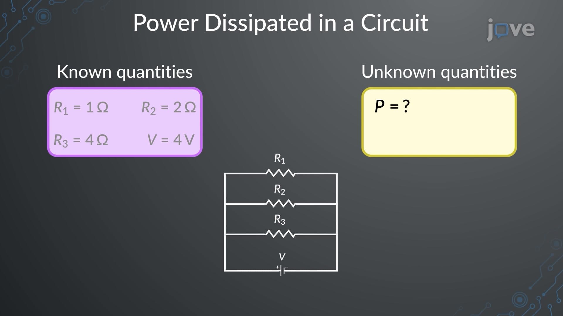
In series combinations, resistors are connected end-to-end, creating a single path for current flow. The total resistance equals the sum of individual resistances: R(total) = R1 + R2 + R3 + ... This arrangement is commonly found in holiday light strings, where each bulb adds to the total resistance. A key characteristic of series circuits is that current remains constant throughout all components, while voltage divides proportionally based on each resistor's value. When one component fails in a series circuit, the entire circuit stops functioning-explaining why older Christmas lights would go dark when a single bulb burned out.
Parallel Resistor Combinations
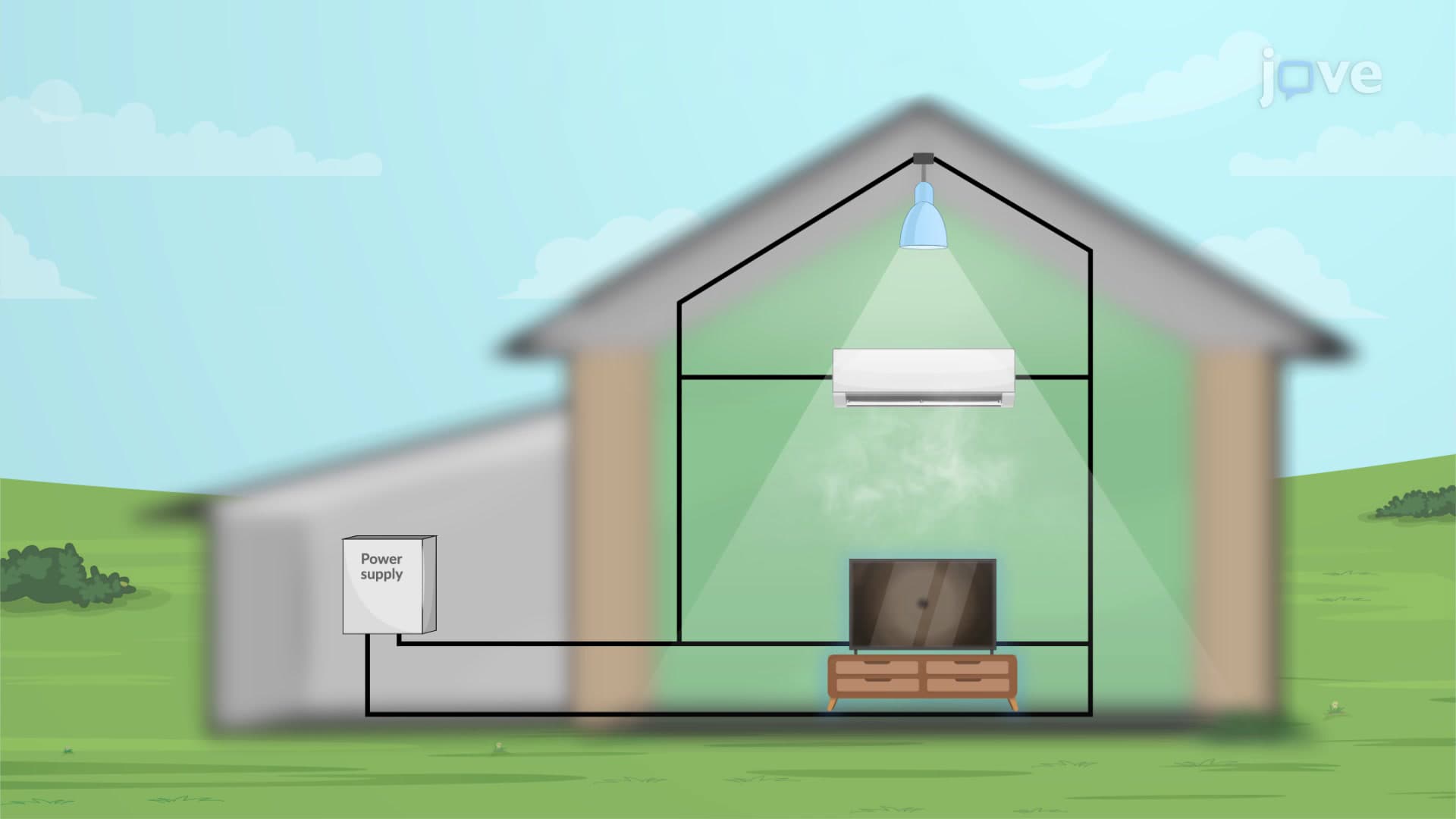
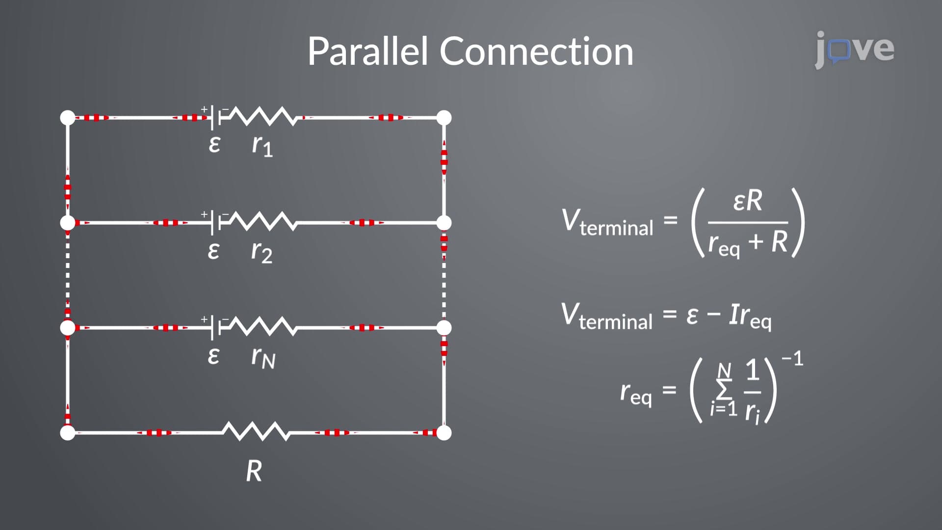
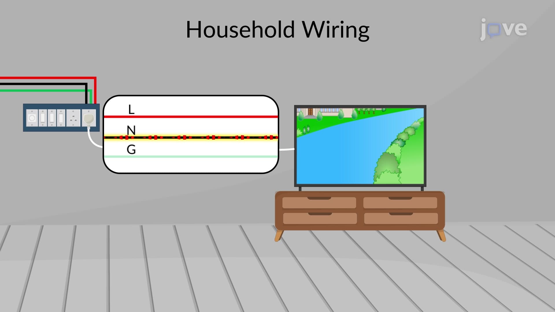
Parallel combinations connect resistors across common points, providing multiple pathways for current flow. The reciprocal of total resistance equals the sum of reciprocals of individual resistances: 1/R(total) = 1/R1 + 1/R2 + 1/R3 + ... This configuration appears in household electrical systems, where outlets, lights, and appliances operate independently. In parallel circuits, voltage remains constant across all branches, while current divides based on each path's resistance. This design ensures that when one device fails, others continue operating normally-crucial for home electrical safety and functionality.
Mixed Circuit Analysis and Real-World Applications
Mixed circuits combine series and parallel elements, requiring systematic analysis to determine electrical behavior. Engineers use equivalent resistance techniques, progressively simplifying parallel sections into single resistors, then analyzing the resulting series circuit. This approach is fundamental in designing electronic devices like smartphones, where different components require specific voltage and current levels. Understanding these concepts proves invaluable for students taking AP Physics C: Electricity and Magnetism, college-level circuit analysis courses, or preparing for engineering entrance exams. The methodology also appears frequently in MCAT physics sections, where test-takers must quickly identify circuit types and apply appropriate solving strategies.
Frequently Asked Questions
Combination of resistors involves connecting multiple resistive elements in series, parallel, or mixed arrangements to control current and voltage in electrical circuits. Understanding these configurations is essential for analyzing everything from simple battery-powered devices to complex electronic systems, and forms the foundation for advanced electrical engineering concepts taught in AP Physics and college-level courses.
AP Physics C: Electricity and Magnetism frequently includes combination resistor problems requiring students to calculate equivalent resistance, current distribution, and power dissipation. These questions often present complex circuit diagrams where students must systematically simplify parallel sections, apply Ohm's law, and demonstrate understanding of current and voltage relationships in both series and parallel configurations.
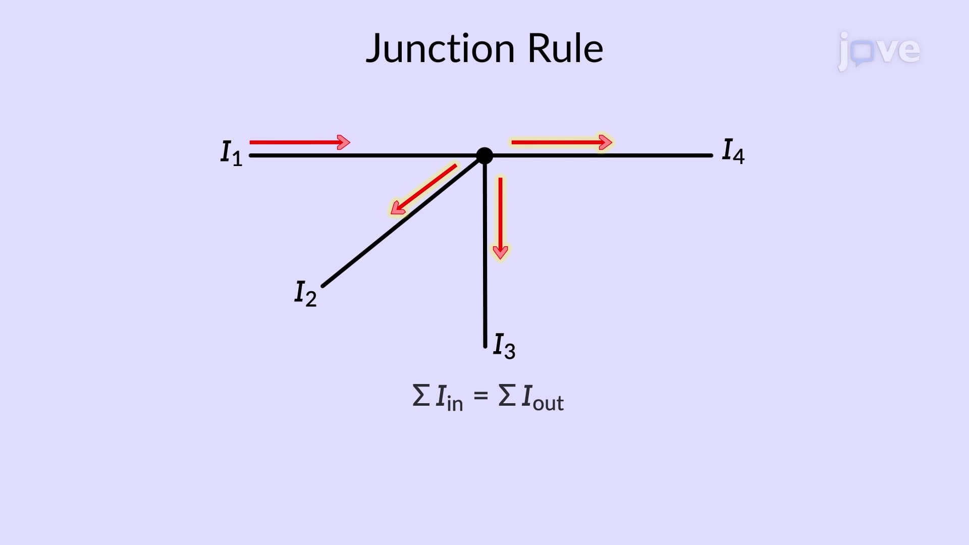
Start by identifying series versus parallel sections, then systematically calculate equivalent resistances working from the most complex parallel groups inward. Always check your units, ensure current conservation at junctions, and remember that voltage drops must sum to the source voltage in complete circuit loops-these fundamental principles will guide you through even complex combination problems.
Not at all-resistor combination problems primarily require basic algebra and the ability to work with fractions. Students who have completed Algebra II can successfully master these concepts, as they rely more on systematic problem-solving approaches than complex mathematical operations. The key is understanding the physical principles behind current flow and voltage distribution.
Combination resistor circuits are everywhere in American households: your car's dashboard lighting system uses parallel resistors to ensure individual gauges work independently, while LED strip lights often employ series resistors for current limiting. Even your laptop's charging circuit contains sophisticated resistor combinations to regulate power delivery and protect sensitive components.
Progress to capacitive and inductive circuits, which introduce time-dependent behavior in AC analysis. Advanced topics include Kirchhoff's laws for complex networks, Thevenin and Norton equivalent circuits, and eventually AC circuit analysis with impedance-all building naturally from the resistor combination foundation you've established.
Practice identifying circuit types quickly, memorize the key formulas for series and parallel resistance, and work through progressively complex mixed circuits. Focus on drawing clear diagrams, labeling current directions, and checking your work using conservation principles-these habits will serve you well in university-level electrical engineering courses.
Related Micro-courses

12 Concepts

22 Concepts
21 Concepts