Loading video…


 18 Concepts
 52.4K views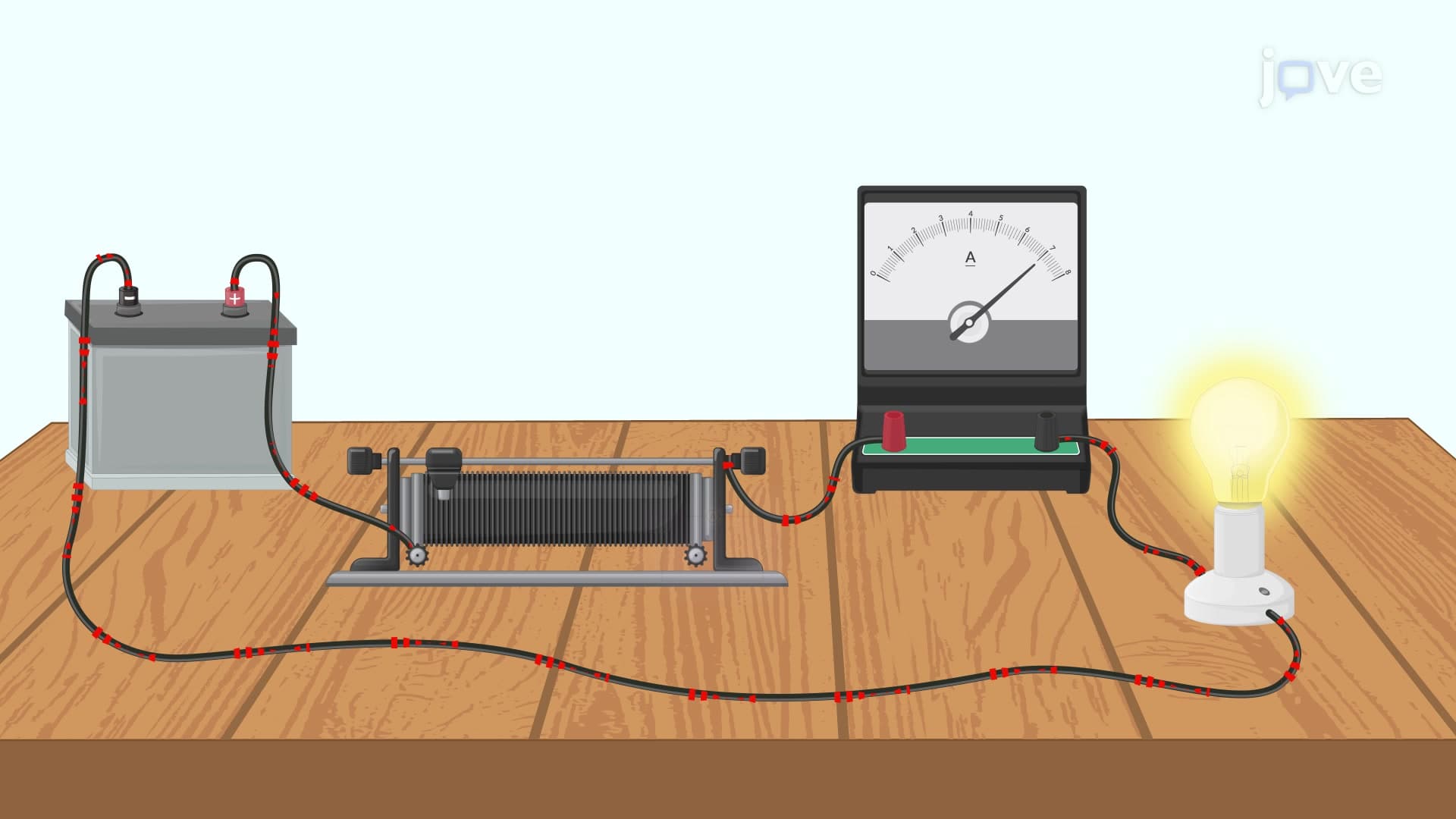

Video Summary: What Is Ammeter
Ever wondered how electricians measure the current flowing through your home's electrical circuits to prevent dangerous overloads? An ammeter serves as the essential electrical measuring instrument that determines current values by connecting in series with circuit elements. Unlike idealized versions with zero resistance, real ammeters possess minimal but finite resistance to avoid altering the circuit's behavior during measurement. U.S. power grid technicians rely on sophisticated ammeters to monitor transmission line currents safely. Watch the full video on JoVE Coach to master this concept with expert-led visuals and step-by-step explanations.
An ammeter represents one of the most fundamental measuring instruments in electrical engineering, designed specifically to quantify electric current flowing through circuit components. Unlike voltmeters that measure potential differences across elements, ammeters must be connected in series with the component being measured, becoming part of the current path itself. This series connection ensures that the identical current flows through both the ammeter and the measured component.
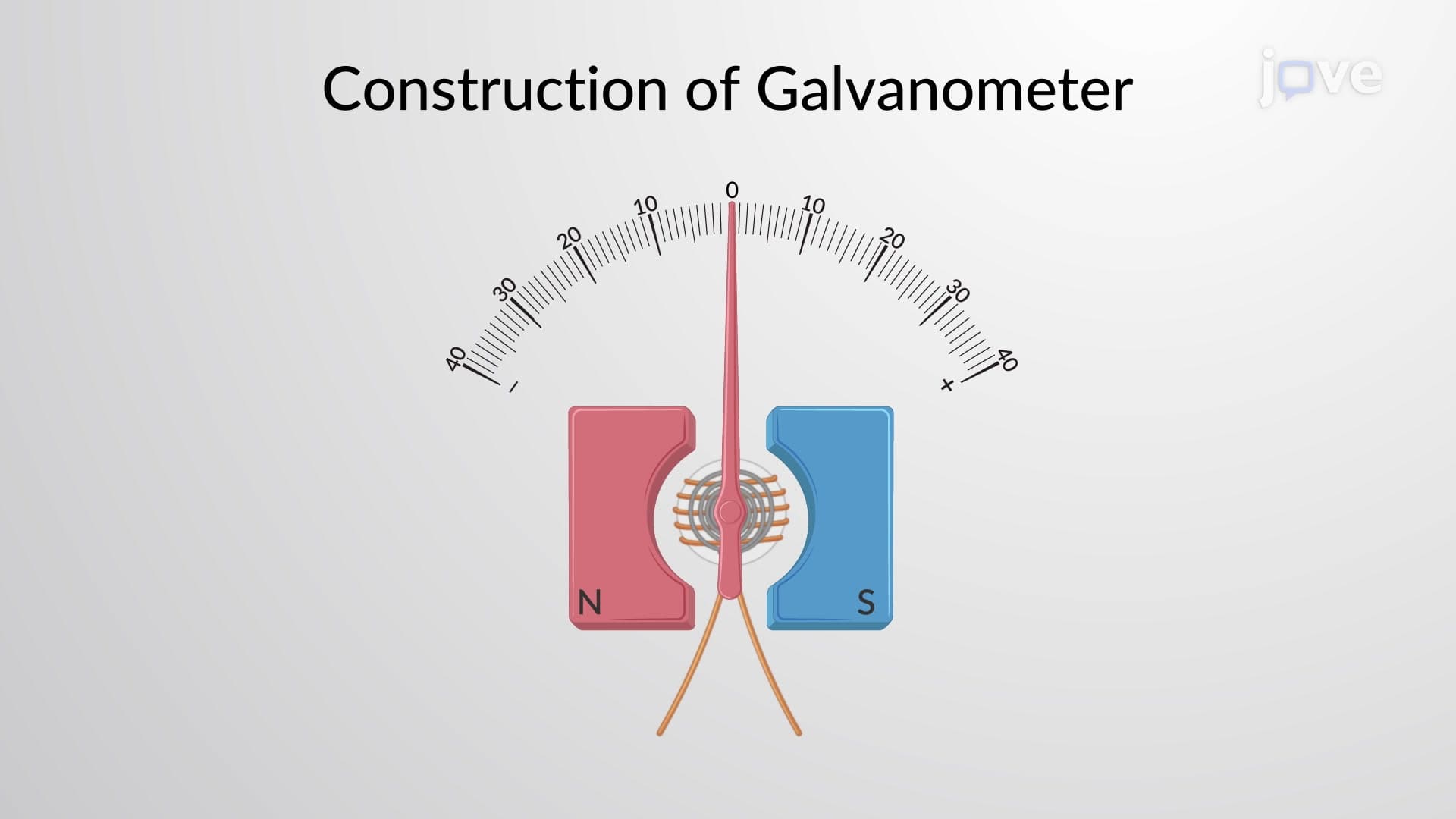
The physics underlying ammeter operation centers on the galvanometer principle, where current-carrying conductors experience forces in magnetic fields. When current passes through the ammeter's internal coil positioned within a magnetic field, the resulting electromagnetic force produces proportional deflection, providing visual or digital current readings.
Theoretical ammeter models assume zero internal resistance, ensuring no voltage drop across the measuring instrument. This idealization prevents circuit modification during measurement, maintaining original current values. However, real ammeters possess finite internal resistance, typically ranging from microohms to milliohms depending on design specifications.
When ammeter resistance becomes significant compared to circuit resistance, measurement accuracy suffers because the ammeter's presence alters the total circuit resistance. For instance, inserting a 0.1-ohm ammeter into a 1-ohm circuit increases total resistance by 10%, correspondingly reducing current by approximately 9%. High-quality ammeters minimize this effect through careful design and material selection.
Practical ammeter design often employs galvanometers with parallel-connected shunt resistors to extend measurement ranges beyond the galvanometer's full-scale deflection current. This configuration divides the total measured current between the galvanometer and shunt paths, with most current flowing through the low-resistance shunt.
The shunt resistance calculation involves equating voltage drops across parallel branches: V(galvanometer) = V(shunt). Since both components share identical voltage drops, the current distribution depends on their relative resistance values. For measuring currents 10 times greater than galvanometer capacity, the shunt resistance must be one-ninth the galvanometer's coil resistance.
U.S. electrical technicians routinely use clamp-on ammeters to measure AC currents in power distribution systems without circuit interruption. These instruments employ electromagnetic induction principles, detecting magnetic fields surrounding current-carrying conductors. Similarly, automotive technicians use digital ammeters to diagnose charging system problems in vehicles.
Students preparing for AP Physics, SAT Subject Tests, or college-level circuit analysis courses frequently encounter ammeter problems involving series circuit calculations and measurement accuracy considerations. Understanding ammeter principles proves essential for MCAT physical sciences sections addressing electrical circuits and instrumentation.
Related Micro-courses