Loading video…


 18 Concepts
 52.4K views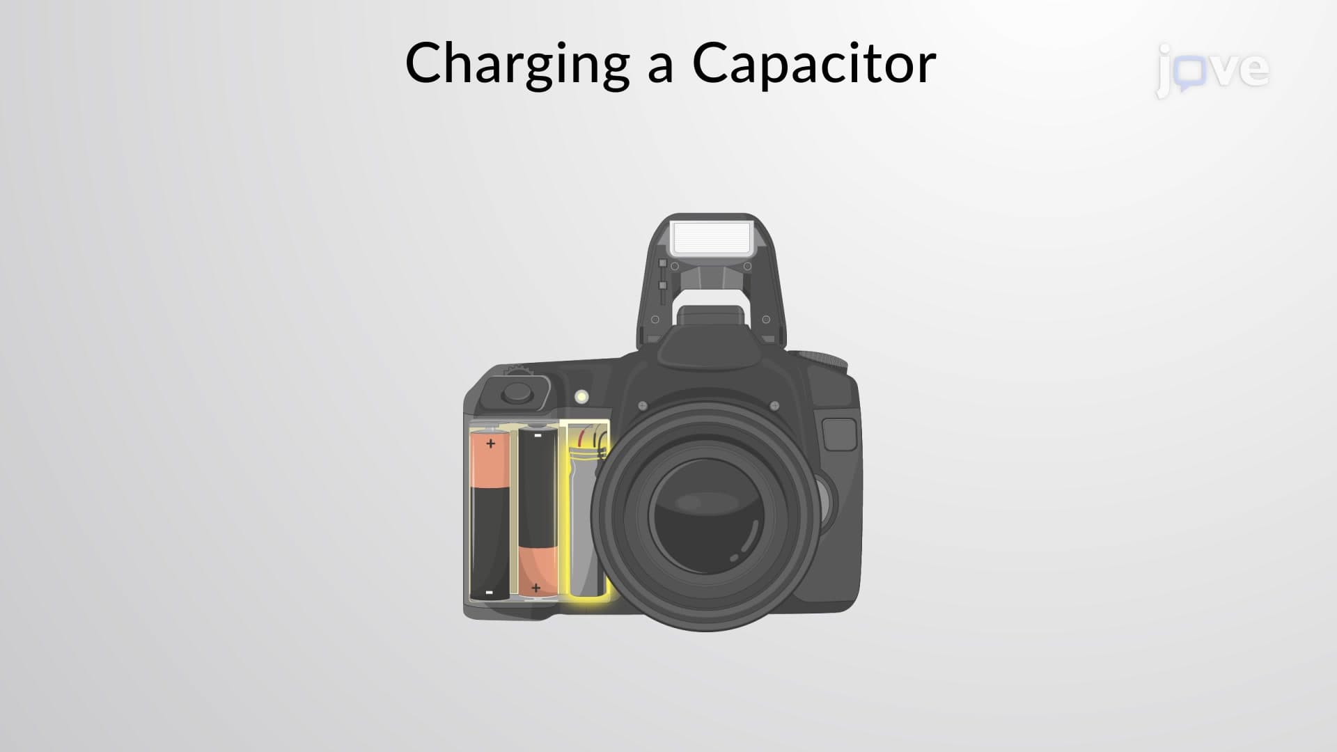

Video Summary: Rc Circuits Charging a Capacitor Explained
Ever wonder how your smartphone's camera flash delivers that instant burst of light? RC circuits charging a capacitor make this everyday technology possible, storing electrical energy that releases in milliseconds. Understanding how RC circuits charging a capacitor works is fundamental to electronics, from camera flashes to defibrillators used in US hospitals. The charging process follows predictable exponential patterns governed by time constants and Kirchhoff's voltage law. Watch the full video on JoVE Coach to master this concept with expert-led visuals and step-by-step explanations.
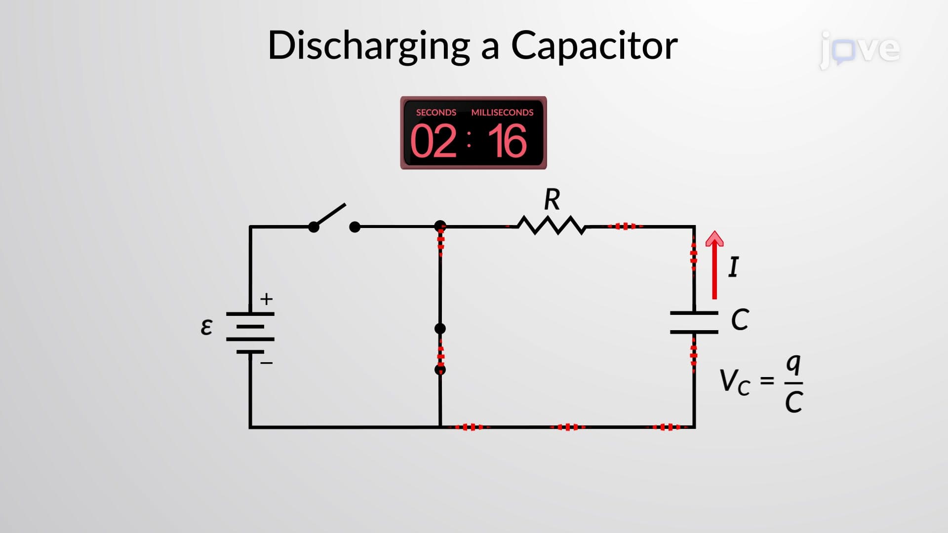
RC circuits charging a capacitor represent one of the most important concepts in introductory electronics and physics. When you connect a resistor and capacitor in series with a DC voltage source, the resulting circuit exhibits fascinating time-dependent behavior that governs countless electronic applications. The charging process begins the moment you close the circuit switch, initiating an exponential approach toward equilibrium.
The charging behavior follows Kirchhoff's voltage law: V(battery) = V(resistor) + V(capacitor). Since V(resistor) = I×R and V(capacitor) = Q/C, we get V(battery) = I×R + Q/C. This leads to the differential equation dQ/dt + Q/(RC) = V(battery)/R. Solving this yields Q(t) = C×V(battery)×(1 - e^(-t/RC)), where RC represents the time constant τ (tau).
The charging current follows I(t) = (V(battery)/R)×e^(-t/RC), starting at its maximum value V(battery)/R when t=0 and decaying exponentially toward zero. Meanwhile, the capacitor voltage grows as V(capacitor)(t) = V(battery)×(1 - e^(-t/RC)), approaching the battery voltage asymptotically.
The RC time constant τ = RC determines charging speed. After one time constant, the capacitor reaches 63.2% of full charge. After five time constants, it's essentially fully charged (99.3%). This principle appears in numerous US applications: camera flashes charge in seconds using small time constants, while larger capacitors in power supplies may require minutes.
Understanding RC charging appears frequently on AP Physics exams, college circuits courses, and the MCAT. Students often encounter problems involving timing circuits, filter applications, and energy storage calculations. For instance, cardiac defibrillators used in US emergency rooms rely on RC charging principles to store life-saving electrical energy. Similarly, the timing circuits in traffic lights and electronic ignition systems in American automobiles utilize RC charging behavior for precise control.
Related Micro-courses