Loading video…


 18 Concepts
 52.4K views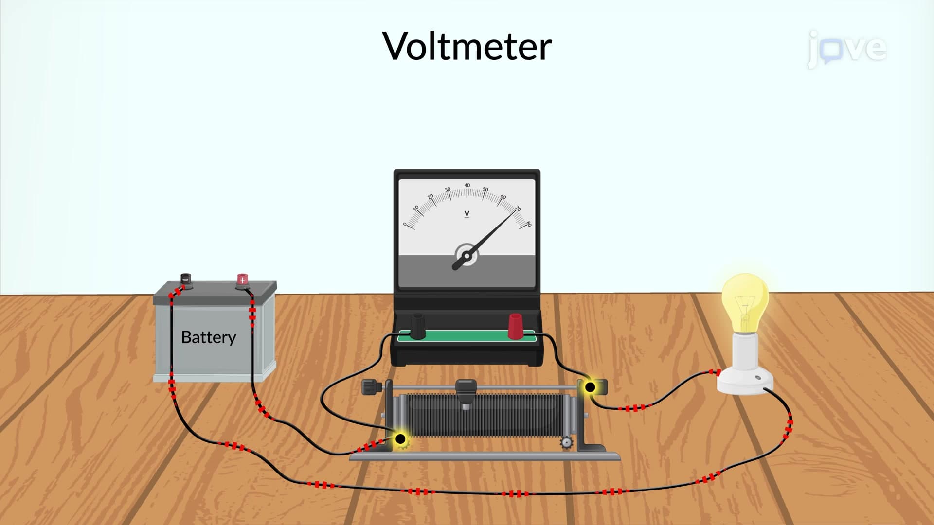

Video Summary: What Is Voltmeter
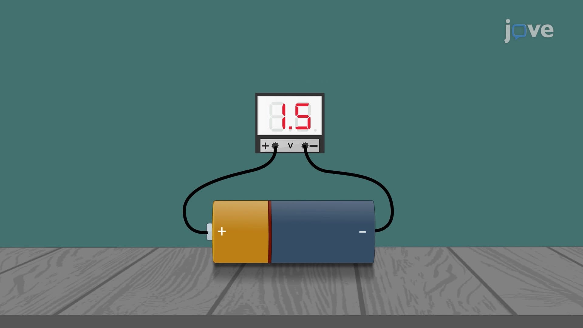
Ever wondered how technicians safely measure the electrical potential in your home's outlets without getting shocked? A voltmeter is the essential instrument that measures voltage by connecting in parallel across circuit elements, requiring high internal resistance to avoid disrupting the circuit. For instance, electrical inspectors across the United States use digital voltmeters to verify that standard household outlets deliver the required 120 volts AC. Understanding what is voltmeter functionality involves recognizing how galvanometers can be converted into voltmeters through series resistor additions. Watch the full video on JoVE Coach to master this concept with expert-led visuals and step-by-step explanations.
A voltmeter represents one of the most crucial measuring instruments in electrical engineering and physics education. Unlike ammeters that measure current flow, voltmeters specifically measure potential difference (voltage) between two points in an electrical circuit. The fundamental voltmeter definition centers on its unique parallel connection method, which allows voltage measurement without significantly disrupting the original circuit conditions.
The voltmeter concept involves understanding the critical distinction between theoretical and practical performance. An ideal voltmeter possesses infinite internal resistance, ensuring zero current draw from the measured circuit. However, real voltmeters exhibit finite resistance, typically ranging from thousands to millions of ohms depending on their design and intended applications.
This voltmeter basics principle becomes particularly important in sensitive electronic circuits where even minimal current draw could affect measurements. For example, when measuring voltage across high-impedance components in audio amplifier circuits used in American-made guitar amplifiers, technicians must use voltmeters with exceptionally high internal resistance to maintain measurement accuracy.
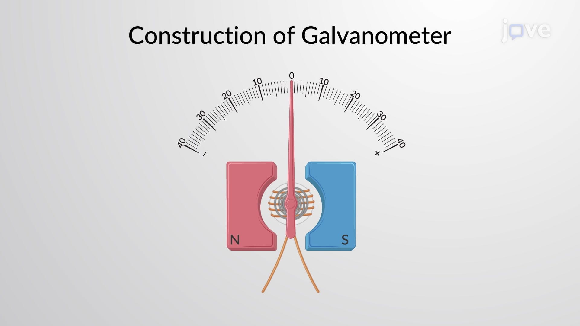
The understanding voltmeter construction involves recognizing how sensitive galvanometers transform into practical voltage-measuring instruments. A galvanometer alone can only measure tiny potential differences, typically in millivolts, with full-scale deflection. Engineers extend this range by adding precision resistors in series with the galvanometer coil.
This series resistor configuration creates a voltage divider circuit where the total measured voltage splits between the galvanometer and the series resistor. By carefully calculating the series resistance value, manufacturers can create voltmeters capable of measuring everything from millivolts to thousands of volts safely.
Students preparing for AP Physics exams frequently encounter voltmeter problems involving circuit analysis and measurement calculations. College-level courses in electrical engineering programs at universities like MIT and Stanford extensively cover voltmeter applications in both DC and AC circuits.
Professional applications span from automotive diagnostics (measuring car battery voltage at 12.6V) to industrial power systems where utility companies monitor transmission line voltages exceeding 500,000 volts using specialized high-voltage voltmeters with appropriate safety ratings and isolation systems.
Related Micro-courses