Loading video…

 10 Concepts
 60 views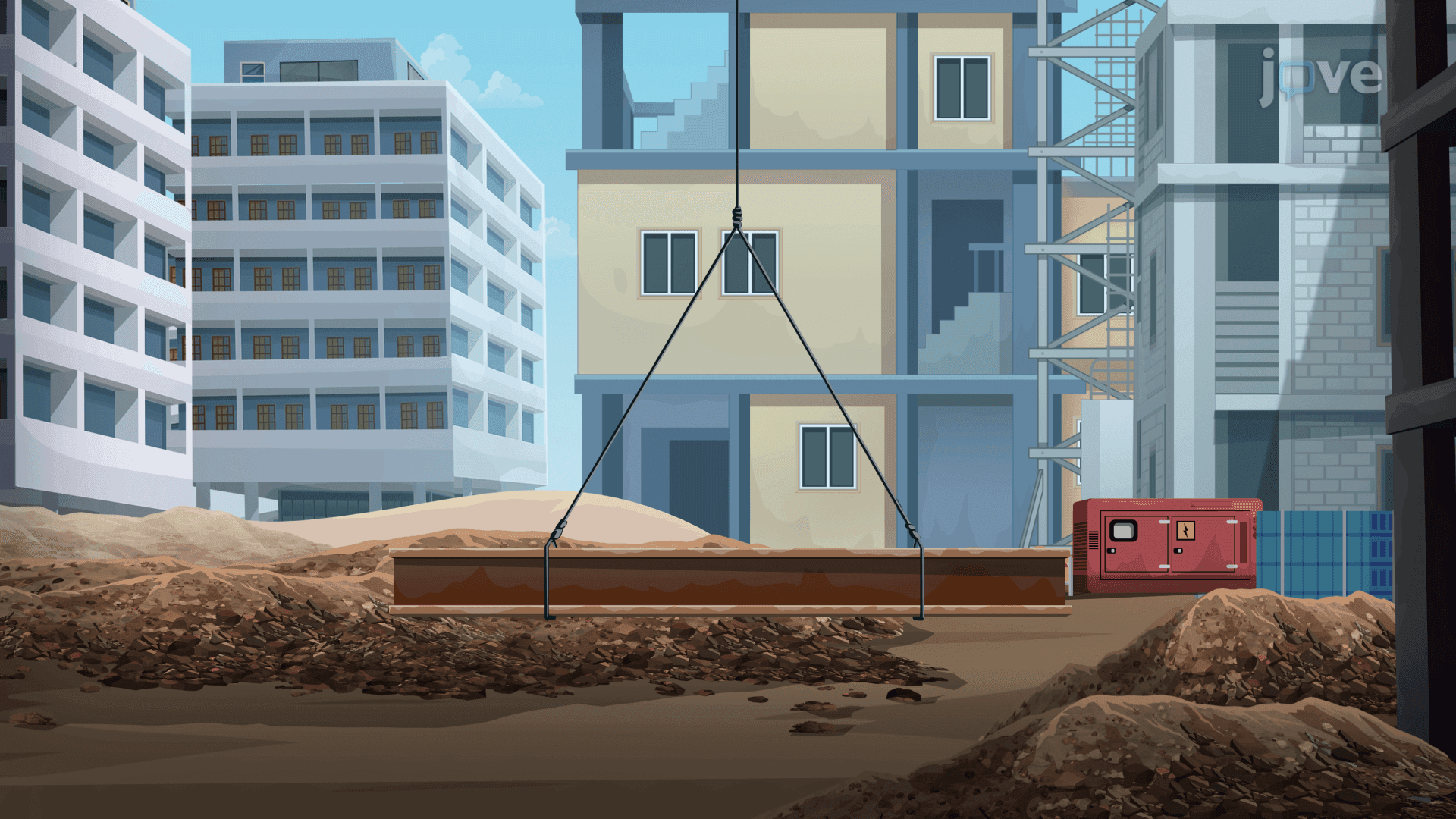

Video Summary: What are Vectors in Engineering Applications
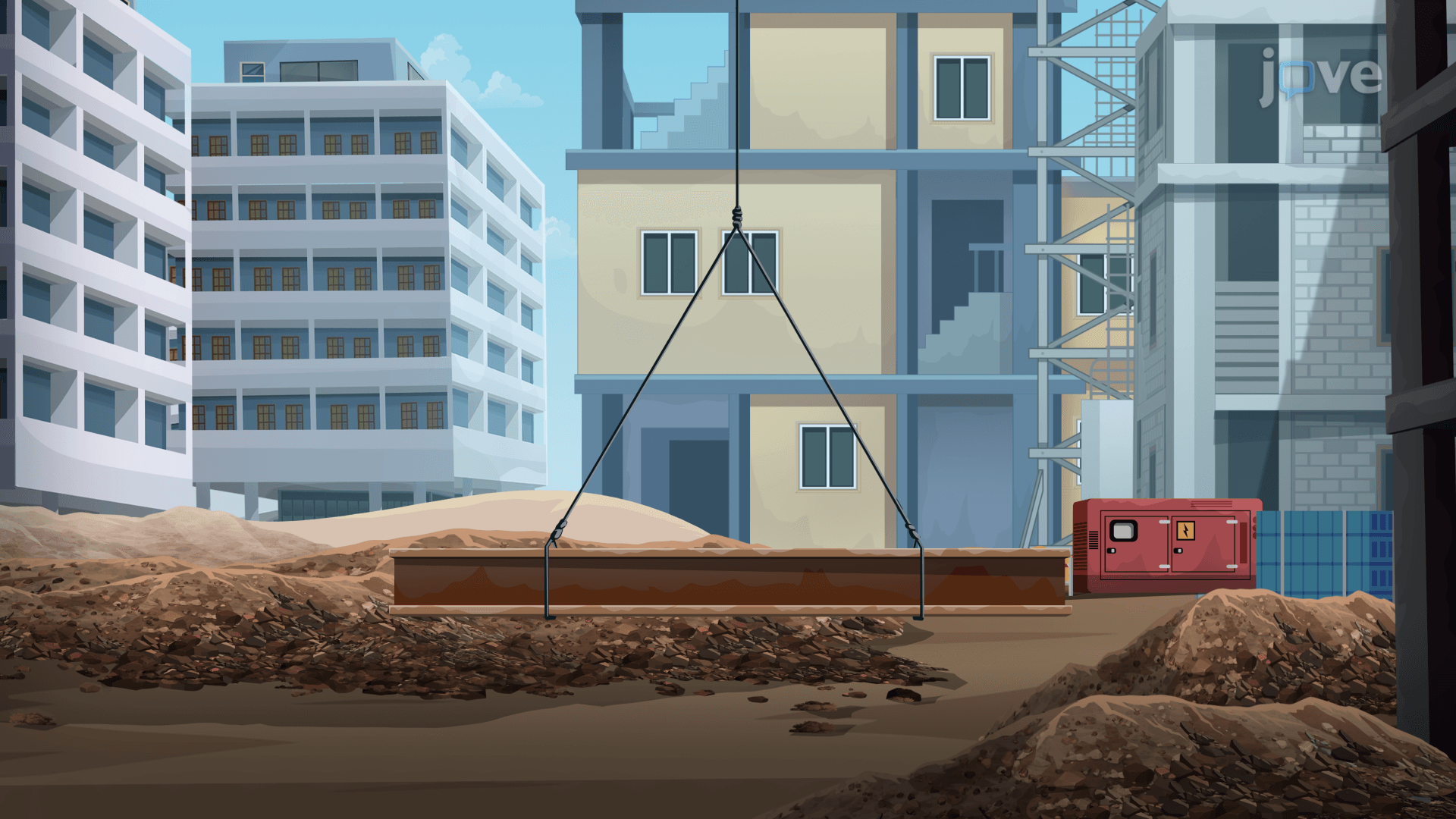
How does a massive steel beam stay perfectly still in mid-air? Vectors in engineering applications make that possible. Understanding vectors in engineering applications basics helps engineers calculate exact cable tensions, like on a real construction site in Chicago or New York, before a single bolt is tightened. By resolving forces into components, engineers guarantee structural safety. Watch the full video on JoVE Coach to master this concept with expert-led visuals and step-by-step explanations.
A number alone cannot describe a force. A bridge cable does not just pull with 5,000 newtons, it pulls at a specific angle, in a specific direction. That is the core insight behind vectors in engineering applications: every physical quantity that has both size and direction must be treated as a vector. Speed becomes velocity. Force gets a direction. And suddenly, the math can tell you whether a structure stands or collapses.
The most practical tool in vector analysis is decomposition. Any vector in a plane can be split into a horizontal component (along unit vector i) and a vertical component (along unit vector j). For a cable making a 60-degree angle with the horizontal, the horizontal component equals T cos(60°) and the vertical component equals T sin(60°). This technique appears constantly in AP Physics 1, AP Physics C: Mechanics, and college-level Statics courses. On the AP Physics 1 exam, free-body diagram problems almost always require students to resolve angled tension or weight forces into components before applying Newton's second law.
Equilibrium means zero net force, the vector sum of all forces equals zero. This produces two independent equations: one for horizontal components and one for vertical components. Solving them simultaneously gives the unknown tension magnitudes. The magnitude of a vector is found using the Pythagorean relationship: |V| = sqrt(Vx² + Vy²). In a symmetric two-cable system, the horizontal components cancel automatically, and the vertical components must together support the full load. This elegant result, that symmetry reduces the algebra, is a concept tested on college engineering midterms and reinforced in courses like Engineering Statics at MIT, Georgia Tech, and Purdue.
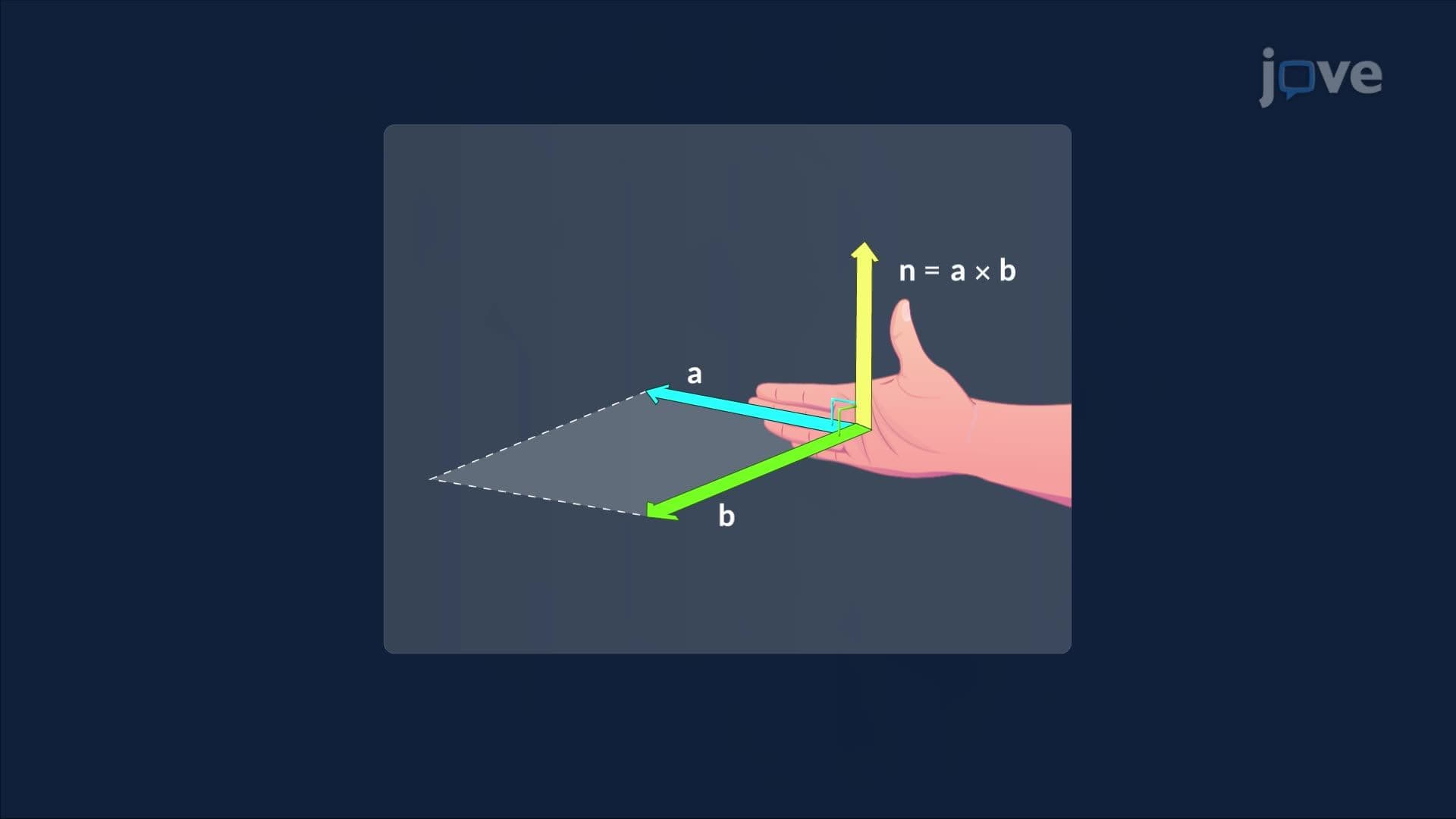
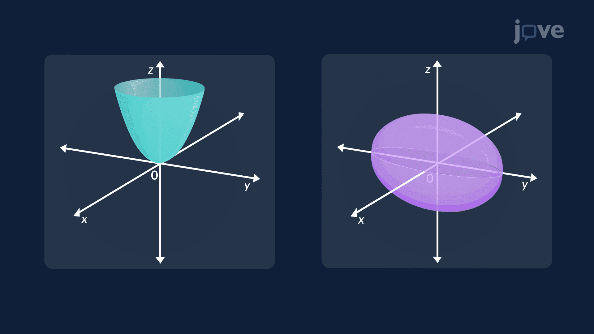
Real engineering structures exist in three dimensions, not two. Direction cosines extend component analysis into 3D by relating a vector's angles with the x, y, and z axes to its components. The dot product measures how much two vectors align, answering questions like "How to find the angle between two vectors?" with the formula: cos(θ) = (A · B) / (|A| |B|). Vector projection uses the dot product to find how much force acts along a structural member. The cross product, whose geometric interpretation is the area of the parallelogram formed by two vectors, gives the torque or moment of a force about a point. These tools also connect to analytic geometry: parametric equations of a line describe force directions in space, equations of planes define structural surfaces, and finding the distance from a point to a plane answers questions about clearance and load offset in mechanical design. Together, these concepts form the mathematical foundation of engineering courses from freshman Calculus III through upper-division Structural Analysis.
Related Micro-courses