Loading subject page…
- Mechanical Engineering
- Planar Kinematics of a Rigid Body
Mechanical Engineering
All Micro-courses:28

1.
Physics Basics
13 Concepts
2.
An Introduction to Statics
10 Concepts
3.
Force Vectors
17 Concepts
4.
Equilibrium of a Particle
6 Concepts
5.
Force System Resultants
20 Concepts
6.
Equilibrium of a Rigid Body
9 Concepts
7.
Structural Analysis
17 Concepts
8.
Internal Forces
14 Concepts
9.
Friction
19 Concepts
10.
Center of Gravity and Centroid
13 Concepts
11.
Moment of Inertia
12 Concepts
12.
Virtual Work
12 Concepts
13.
Kinematics of a Particle
4 Concepts
14.
Kinetics of a Particle: Force and Acceleration
5 Concepts
15.
Kinetics of a Particle: Impulse and Momentum
12 Concepts
16.
Planar Kinematics of a Rigid Body
13 Concepts
17.
3-Dimensional Kinetics of a Rigid Body
10 Concepts
18.
Concept of Stress
8 Concepts
19.
Stress and Strain - Axial Loading
20 Concepts
20.
Torsion
12 Concepts
21.
Bending
18 Concepts
22.
Analysis and Design of Beams for Bending
4 Concepts
23.
Shearing Stresses in Beams and Thin-Walled Members
6 Concepts
24.
Transformations of Stress and Strain
10 Concepts
25.
Principal Stresses under a Given Loading
4 Concepts
26.
Deflection of Beams
9 Concepts
27.
Columns
7 Concepts
28.
Energy Methods
8 Concepts
Planar Kinematics of a Rigid Body
 13 Concepts
 6.9K Views
 Popular topics
Concepts: 13

01:22
693 views
01:26
956 views
01:30
521 views

01:24
364 views
01:24
521 views

01:20
609 views

01:10
550 views
01:25
630 views

01:22
487 views
01:29
517 views

01:18
328 views
01:22
376 views

01:16
312 views
Planar kinematics of a rigid body examines how objects move within a two-dimensional plane through translation and rotation. This fundamental engineering concept applies to countless real-world systems, from subway trains and roller coasters to drone flight dynamics and automotive engines. Master these principles with JoVE Coach to understand complex mechanical systems in aerospace, robotics, and manufacturing industries.
- Understand the three fundamental types of planar rigid body motion: rectilinear translation, curvilinear translation, and rotation
- Analyze angular velocity, acceleration, and displacement using kinematic equations for rotational motion
- Apply absolute motion analysis to solve complex general plane motion problems in mechanical systems
- Identify instantaneous centers of zero velocity to simplify velocity calculations in rolling and rotating bodies
- Explore relative motion analysis techniques using both translating and rotating reference frames
- Analyze acceleration relationships in rotating axes for advanced mechanical system problems
- Apply equations of motion for rigid bodies rotating about fixed axes and in general plane motion
- Solve real-world engineering problems involving slider-crank mechanisms, gears, and rotating machinery
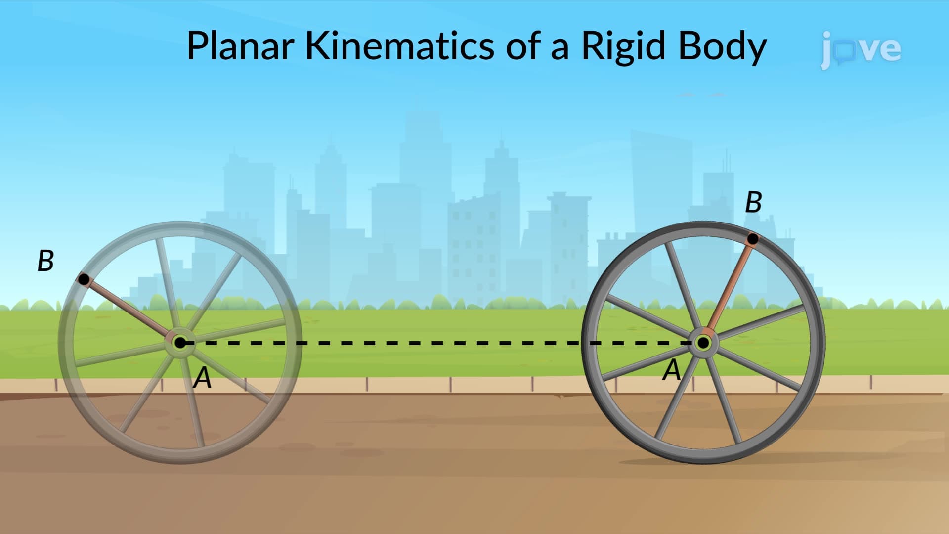
1. Types of Planar Rigid Body Motion Understanding how rigid bodies move in planes reveals three distinct motion categories. Rectilinear translation occurs when objects like subway trains move in straight lines while maintaining orientation. Curvilinear translation happens when bodies like roller coaster cars follow curved paths but don't rotate. Rotation about a fixed axis describes spinning objects like wind turbines, where particles trace circular paths around a central axis. General planar motion combines translation and rotation simultaneously, exemplified by a thrown football that spins while traveling through the air, creating complex motion patterns essential for analyzing real mechanical systems.
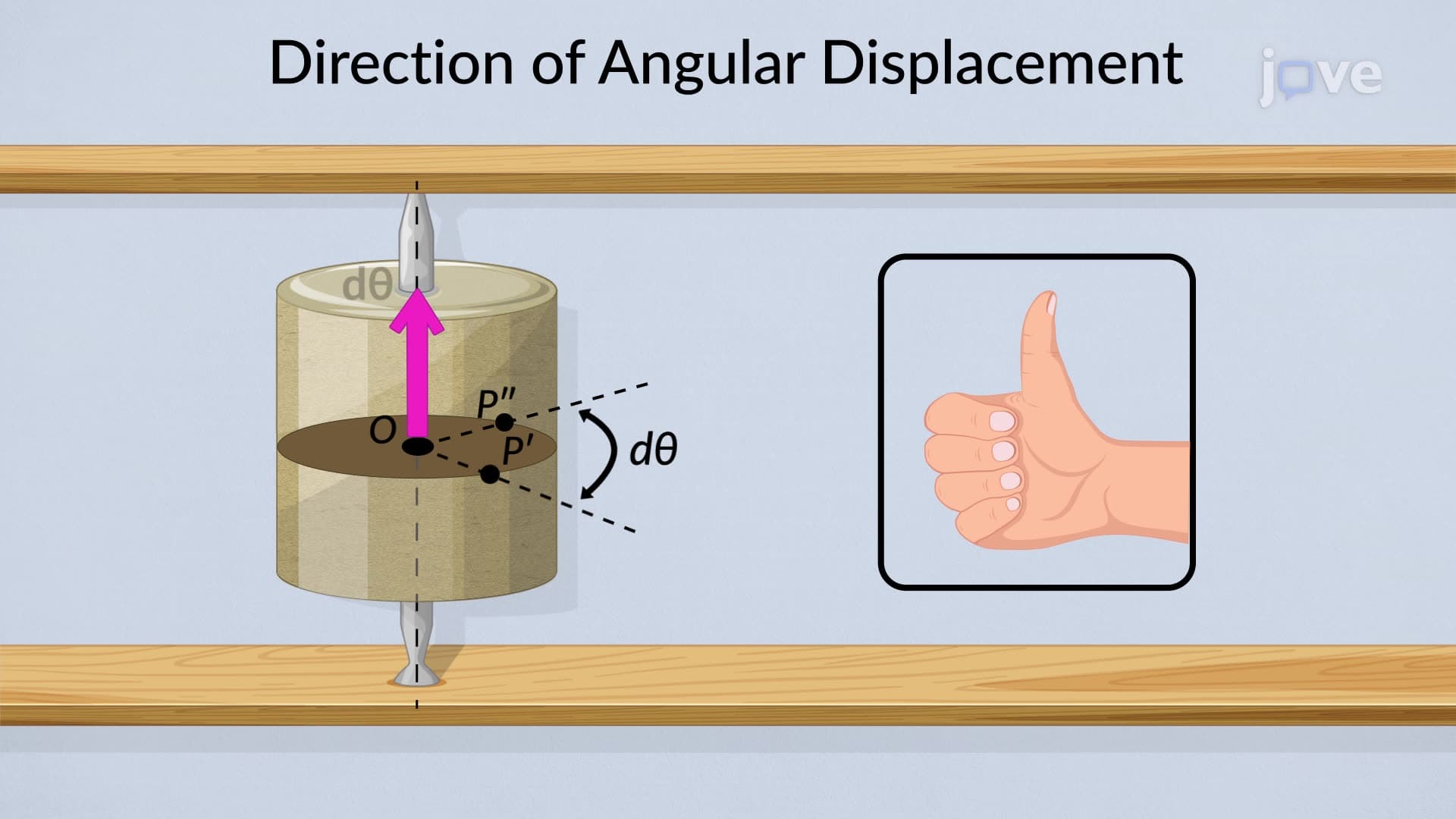
2. Angular Kinematics and Mathematical Relationships Angular motion parallels linear motion through three fundamental quantities. Angular displacement (θ) measures rotational position changes from reference lines, typically expressed in radians. Angular velocity (ω) describes rotation rate in radians per second, following the right-hand rule for direction. Angular acceleration (α) represents how quickly angular velocity changes, measured in radians per second squared. These quantities relate through kinematic equations similar to linear motion: ω = dθ/dt and α = dω/dt. For constant angular acceleration, familiar equations apply: ω = ω₀ + αt and θ = θ₀ + ω₀t + ½αt².
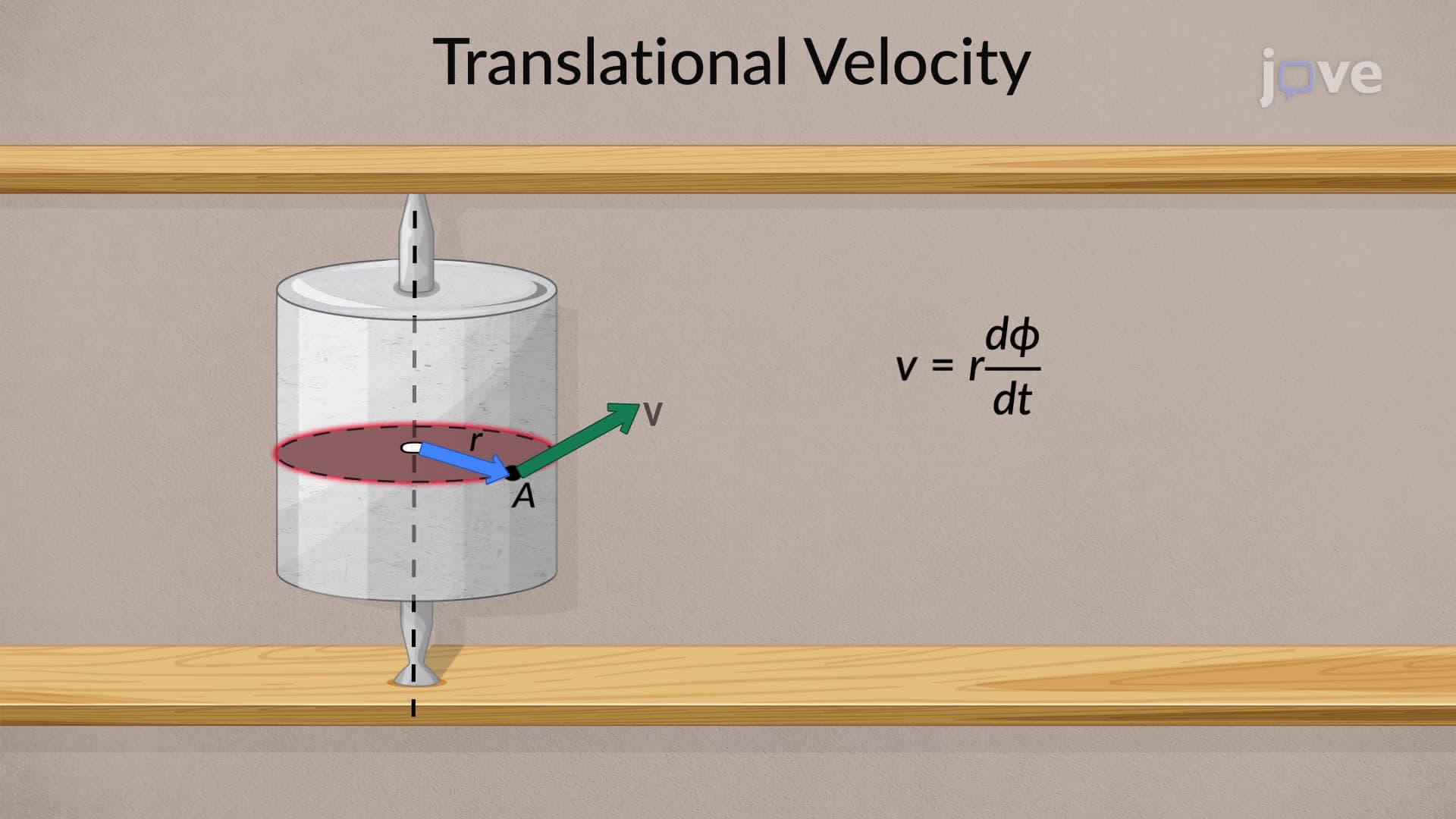
3. Velocity and Acceleration in Rotating Bodies Points on rotating rigid bodies exhibit specific velocity and acceleration characteristics. The velocity of any point equals the cross product of angular velocity and position vector: v = ω × r. This velocity always acts tangentially to the circular path. Acceleration has two components: tangential acceleration (at = α × r) changes speed magnitude, while normal acceleration (an = ω²r) changes direction, always pointing toward the rotation center. Understanding these relationships helps analyze complex systems like helicopter rotors, where blade tips experience enormous accelerations, or automotive wheels during acceleration and braking maneuvers.
4. Instantaneous Center of Zero Velocity Method The instantaneous center technique simplifies velocity analysis by identifying points with momentarily zero velocity. For rolling wheels, this center lies at ground contact points, making velocity calculations straightforward using v = ωr relationships. This method proves invaluable for analyzing gear trains, linkage mechanisms, and robotic arms. In automotive applications, understanding instantaneous centers helps optimize transmission designs and analyze suspension geometry. The center location changes continuously during motion, requiring careful analysis of each instant to properly characterize system behavior and optimize mechanical performance.
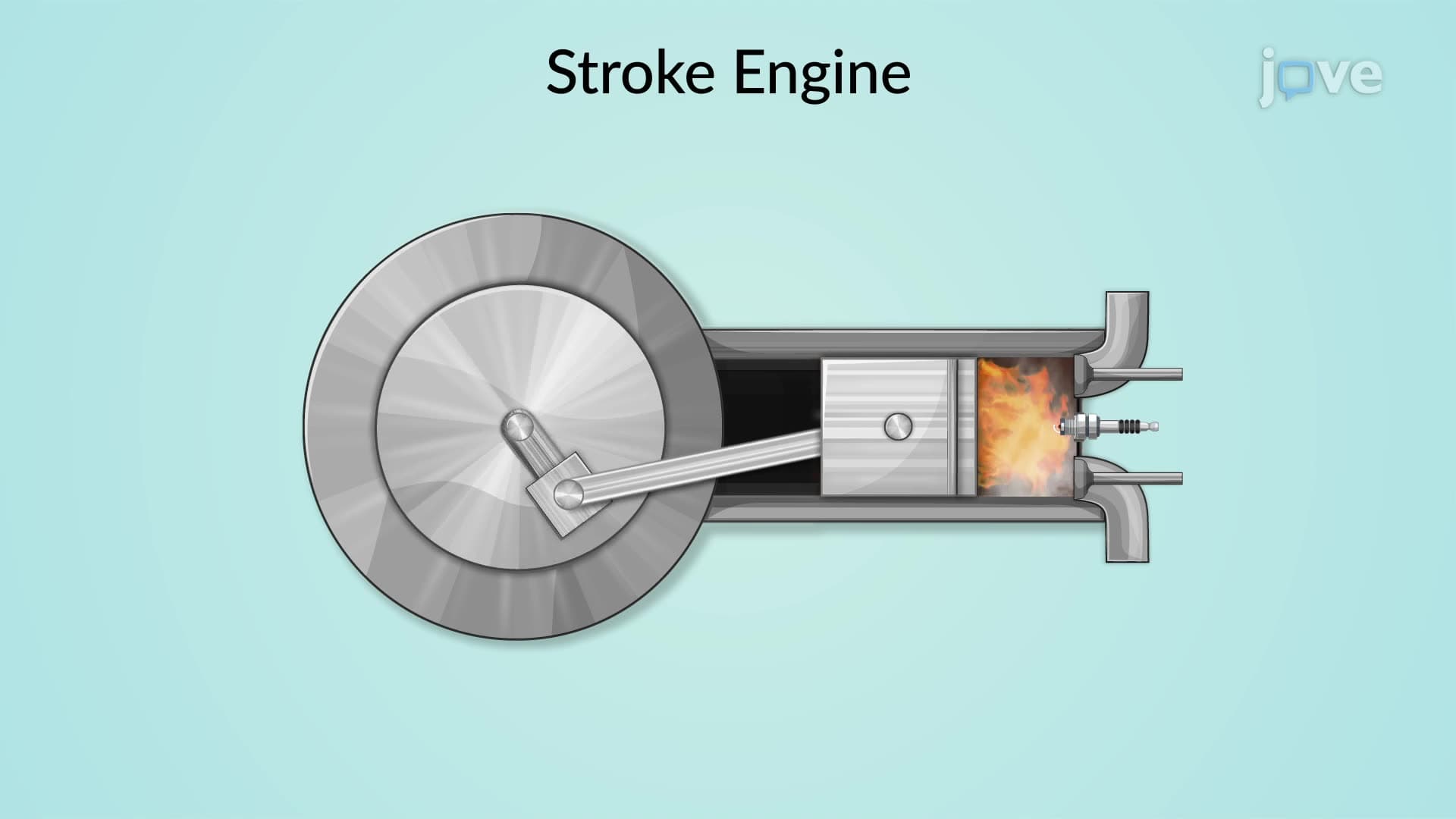
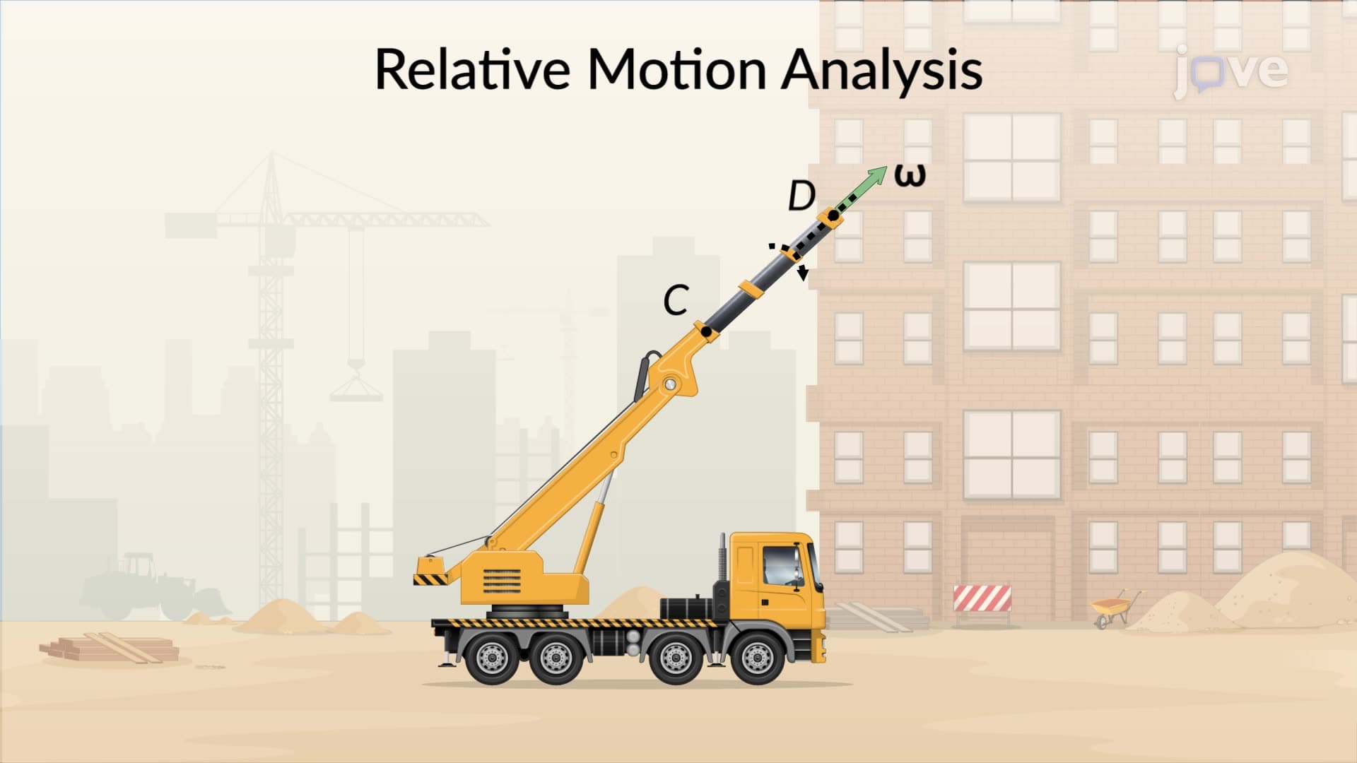
5. Relative Motion Analysis Using Reference Frames Analyzing complex motions requires strategic reference frame selection. Translating frames simplify problems where one point undergoes known motion while others move relative to it. The fundamental equation vB = vA + vB/A expresses absolute velocities as vector sums of reference point velocity and relative velocity. Rotating reference frames add complexity through angular velocity effects: vB = vA + vB/A + ω × rB/A. This approach proves essential for analyzing slider-crank mechanisms in internal combustion engines, where connecting rods undergo complex combined motions that determine piston velocities and accelerations.
6. Acceleration Analysis in Rotating Reference Frames Acceleration analysis in rotating frames introduces additional complexity through Coriolis and centripetal effects. The complete acceleration equation includes translating frame acceleration, relative acceleration within the rotating frame, and two angular velocity terms. One term represents tangential acceleration from angular acceleration, while another accounts for velocity changes due to frame rotation. These effects become crucial in aerospace applications, where aircraft or spacecraft maneuvers create complex acceleration environments. Understanding these principles helps design control systems and predict structural loads in rotating machinery like turbines and centrifuges.
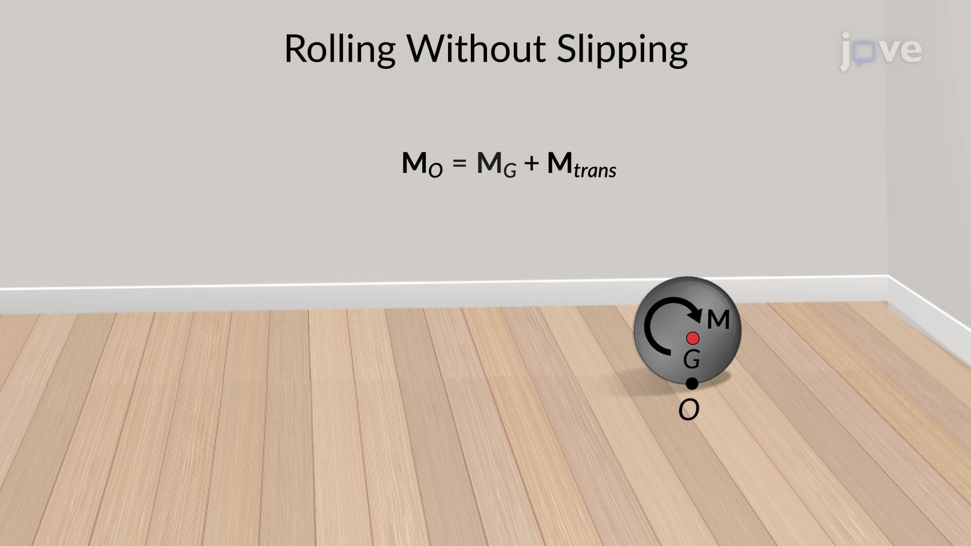
7. Equations of Motion for Rigid Body Dynamics Newton's laws extend to rigid body motion through translational and rotational equations. Linear motion follows ΣF = ma for the center of mass, while rotational motion satisfies ΣM = Iα about the center of mass or any fixed point. For rolling objects, the parallel axis theorem relates moments of inertia: IO = ICM + md². These principles apply to analyzing vehicle dynamics, where wheel rotation couples with translational motion. In robotics, these equations govern joint motions and end-effector positioning. Proper application requires careful selection of coordinate systems and understanding of constraint conditions like rolling without slipping.