Loading subject page…


21 Concepts
14 Concepts
11 Concepts
11 Concepts
16 Concepts
8 Concepts
18 Concepts
12 Concepts
6 Concepts
12 Concepts
6 Concepts
5 Concepts
6 Concepts
9 Concepts
8 Concepts
8 Concepts
7 Concepts
9 Concepts
10 Concepts
8 Concepts
13 Concepts
5 Concepts
11 Concepts
10 Concepts
7 Concepts
6 Concepts
9 Concepts
10 Concepts
6 Concepts
9 Concepts
 12 Concepts
 3.6K Views
 Popular topics






Creep in concrete represents one of the most critical time-dependent deformation mechanisms affecting structural performance. This comprehensive course explores concrete deformation properties including elastic behavior, time-dependent deformation in concrete, and shrinkage phenomena. Through detailed analysis of testing methods, environmental factors, and real-world applications in American infrastructure projects, students master essential concepts for structural engineering success with JoVE Coach guidance.
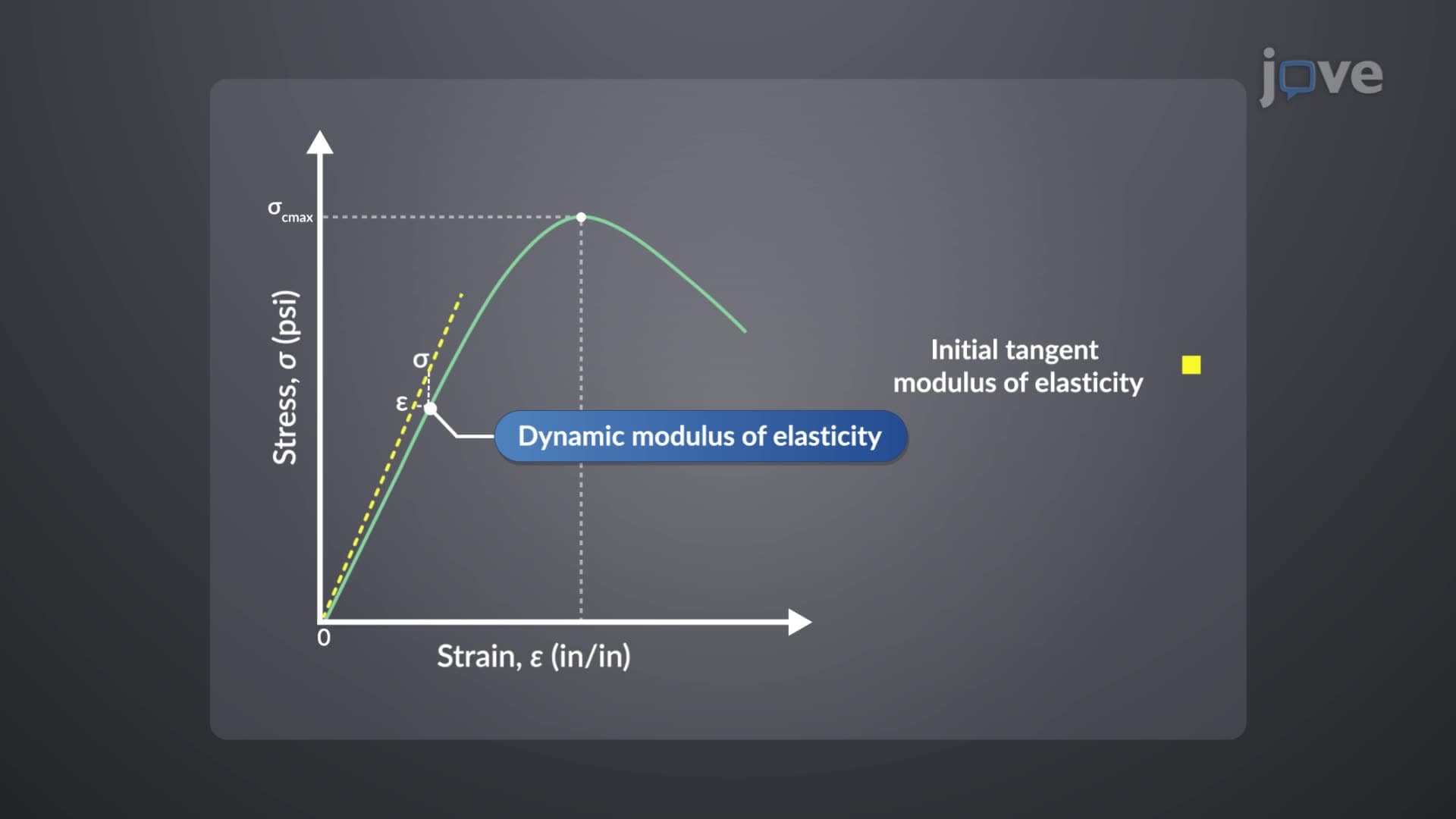
1. Static and Dynamic Modulus of Elasticity The elastic modulus concrete exhibits varies significantly between static and dynamic loading conditions. Static modulus determination involves three primary methods: tangent modulus (slope of tangent line at any stress point), secant modulus (slope from origin to 40% ultimate load point), and chord modulus (slope between 50 microinches/inch strain and 40% ultimate load). Dynamic modulus, essential for earthquake-resistant design in California buildings, is measured using sonic testing with electromagnetic excitation. The Golden Gate Bridge's concrete towers demonstrate dynamic modulus applications in seismic zones, where dynamic values exceed static measurements by 20-40%.
2. Creep Mechanisms and Fundamentals Creep in concrete occurs when sustained loads cause continued deformation over time, primarily due to moisture loss from calcium silicate hydrate gel in cement paste. This time-dependent deformation in concrete results from microcrack propagation in interfacial transition zones and stress transfer from paste to aggregates. The Willis Tower in Chicago experiences measurable creep in its concrete core, demonstrating how long-term deformation affects high-rise structures. Creep exhibits both immediate elastic recovery upon unloading and gradual creep recovery, though permanent residual deformation always remains in the structural member.
3. Factors Influencing Creep Behavior Multiple variables affect concrete compliance and creep magnitude. Aggregate properties play crucial roles-high-modulus aggregates like granite reduce creep compared to limestone aggregates. The creep coefficient increases linearly with applied stress within design limits but becomes non-linear beyond safe stress levels. Water-cement ratio significantly impacts creep: lower ratios produce stronger concrete with reduced creep. Loading age matters critically-concrete loaded after 28 days shows less creep than early-loaded members. The Hoover Dam's mass concrete demonstrates how member size and relative humidity affect creep behavior in large structures.
4. Structural Effects of Creep Time-dependent deformation in concrete produces varied effects across structural systems. Reinforced concrete beams experience increased deflections, potentially causing crack widening and new crack formation. Slender columns under eccentric loads may buckle due to creep-induced deflections, as observed in some parking garage failures. However, creep benefits indeterminate structures by relieving stress concentrations at beam-column connections. Prestressed concrete beams lose prestressing force over time unless high-tensile steel is used. Differential creep in high-rise buildings like New York's One World Trade Center requires careful design consideration for partition and cladding connections.
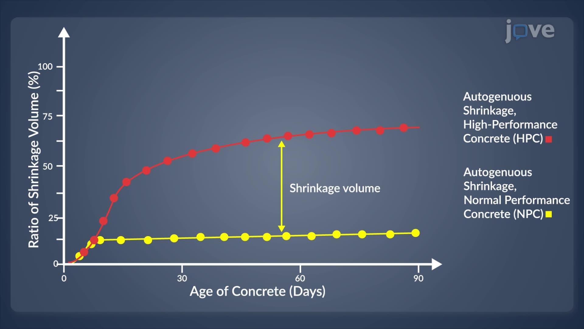
5. Shrinkage Types and Mechanisms Drying shrinkage dominates volume changes in hardened concrete as capillary water evaporates and adsorbed water moves from calcium silicate hydrates. This process partly reverses through wetting expansion when moisture returns. Plastic shrinkage occurs during concrete's fresh state due to surface evaporation, particularly problematic in hot, windy conditions common in Arizona construction projects. Autogenous shrinkage develops internally as cement hydration creates capillary tension, with high-performance concrete showing greater autogenous shrinkage than normal concrete due to low water-cement ratios used in modern skyscraper construction.
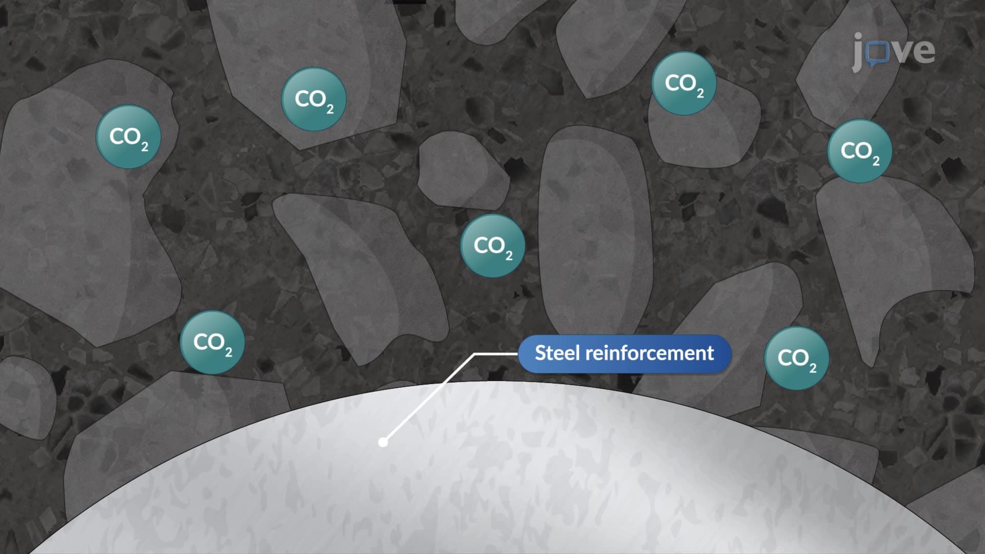
6. Carbonation Shrinkage and Durability Atmospheric carbon dioxide penetrates concrete surfaces, forming carbonic acid that reacts with calcium hydroxide to produce calcium carbonate and water. This carbonation shrinkage process neutralizes concrete's alkaline environment, enabling reinforcement corrosion when oxygen and moisture penetrate. The Brooklyn Bridge's concrete components demonstrate long-term carbonation effects in marine environments. Phenolphthalein testing reveals carbonation depth-pink coloration indicates uncarbonated concrete while colorless areas show carbonation progression. This testing method is standard practice for evaluating concrete durability in aging American infrastructure like interstate highway bridges built during the 1960s expansion.
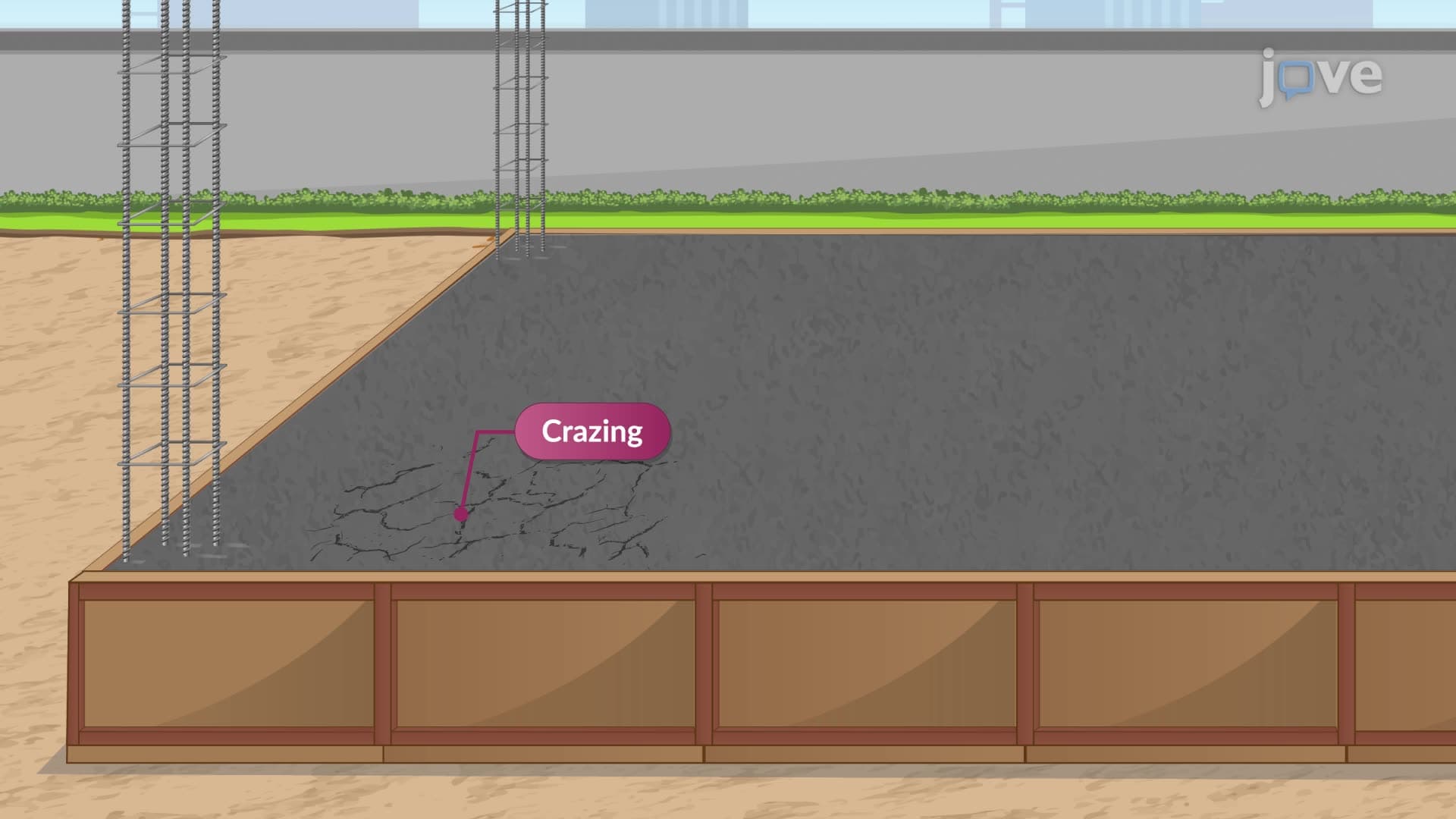
7. Non-Structural Crack Types Various cracking mechanisms affect concrete appearance and performance without compromising structural integrity. Plastic settlement cracks form above reinforcement when rising water settles aggregates, preventable through adequate concrete cover. Plastic shrinkage creates diagonal surface patterns when evaporation-induced tensile stresses exceed concrete's early tensile strength. Surface cracks result from drying shrinkage in externally restrained members, managed through strategic movement joint placement. Early thermal cracks develop when surface cooling creates differential contraction between exterior and interior concrete regions. Crazing produces fine hairline patterns from over-troweling cement-rich surface layers, common in decorative concrete applications.
8. Mass Concreting Techniques Large concrete pours require specialized approaches to prevent thermal cracking from heat of hydration. Low-heat cement and pozzolanic materials like fly ash reduce temperature rise, while chilled mixing water achieves placement temperatures around 45°F. The Hoover Dam's construction pioneered embedded cooling pipes for temperature control in massive concrete sections. Thermally insulating formwork and plastic-coated quilts minimize heat loss, while thermocouples monitor internal temperatures. Construction proceeds in lifts with movement joints to accommodate thermal expansion. These techniques apply to modern projects like nuclear power plant containment structures and large foundation mats for commercial developments.
9. Weather-Dependent Concreting Practices Hot weather concreting limits concrete temperature to 60°F maximum through ice addition to mixing water, aggregate shading, and evening placement schedules. Phoenix construction projects routinely employ white-painted equipment and water-cooled aggregate stockpiles. Cold weather concreting below 40°F uses heated aggregates, Type III cement, and accelerating admixtures to prevent freeze-thaw damage. Insulating blankets and heated enclosures protect concrete during initial curing periods. Minnesota winter construction demonstrates successful cold weather techniques including steam-heated aggregates and continuous temperature monitoring through embedded thermocouples to ensure proper strength development.