Loading subject page…
- Civil Engineering
- Horizontal and Vertical Curves
Civil Engineering
All Micro-courses:30

1.
Masonry Materials
21 Concepts
2.
Masonry
14 Concepts
3.
Wood
11 Concepts
4.
Introduction to Concrete
11 Concepts
5.
Aggregates and Water
16 Concepts
6.
Fresh Concrete
8 Concepts
7.
Strength of Concrete
18 Concepts
8.
Mixing, Placing and Curing Concrete
12 Concepts
9.
Admixtures
6 Concepts
10.
Elasticity, Creep, and Shrinkage in Concrete
12 Concepts
11.
Permeability of Concrete
6 Concepts
12.
Freezing and Thawing in Concrete
5 Concepts
13.
Design Examples
6 Concepts
14.
Fluid Properties
9 Concepts
15.
Fluid Statics
8 Concepts
16.
Fluid Dynamics
8 Concepts
17.
Fluid Kinematics
7 Concepts
18.
Finite Control Volume Analysis
9 Concepts
19.
Differential Analysis of Fluid Flow
10 Concepts
20.
Dimensional Analysis, Similitude, and Modeling
8 Concepts
21.
Flow in Pipes
13 Concepts
22.
Flow over Immersed Bodies
5 Concepts
23.
Open Channel Flow
11 Concepts
24.
Introduction to Surveying
10 Concepts
25.
Leveling
7 Concepts
26.
Angles and Directions
6 Concepts
27.
Traverse and Topographic Surveying
9 Concepts
28.
Horizontal and Vertical Curves
10 Concepts
29.
Global Positioning System (GPS)
6 Concepts
30.
Geographic Information Systems (GIS)
9 Concepts
Horizontal and Vertical Curves
 10 Concepts
 2.2K Views
 Popular topics
Concepts: 10
01:19
349 views
01:19
287 views
01:17
128 views
01:03
180 views
01:26
242 views

01:24
297 views
01:23
264 views
01:20
120 views

01:29
185 views
01:09
113 views
Horizontal curves form the foundation of safe road alignment curves in US highway systems, enabling smooth transitions between straight roadway segments. This comprehensive course covers the design of horizontal and vertical alignment curves, from basic circular geometry to advanced sight distance calculations. Students will master curve staking procedures, vertical curve analysis, and real-world applications using JoVE Coach methodology essential for transportation engineering careers.
- Understand the geometric principles of simple circular curve design and radius of curvature calculations
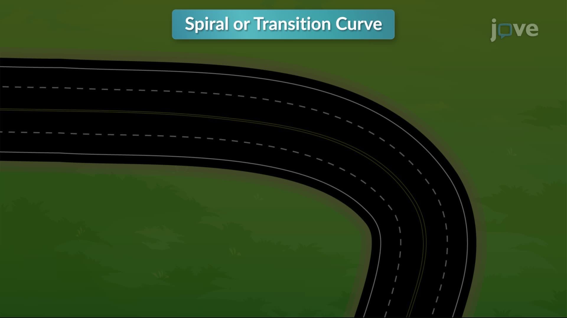
- Learn to differentiate between horizontal curves, compound curves, reverse curves, and spiral curves
- Identify key curve elements including points of curvature, tangency, and intersection in road alignment
- Explore degree of curvature concepts using both chord basis and arc basis methods
- Analyze vertical curve road transitions and parabolic curve geometry for grade changes
- Apply field staking procedures for accurate curve construction and alignment design
- Calculate sight distances on vertical curves for safe highway design standards
- Understand tangent offset methods for determining elevations at intermediate curve points
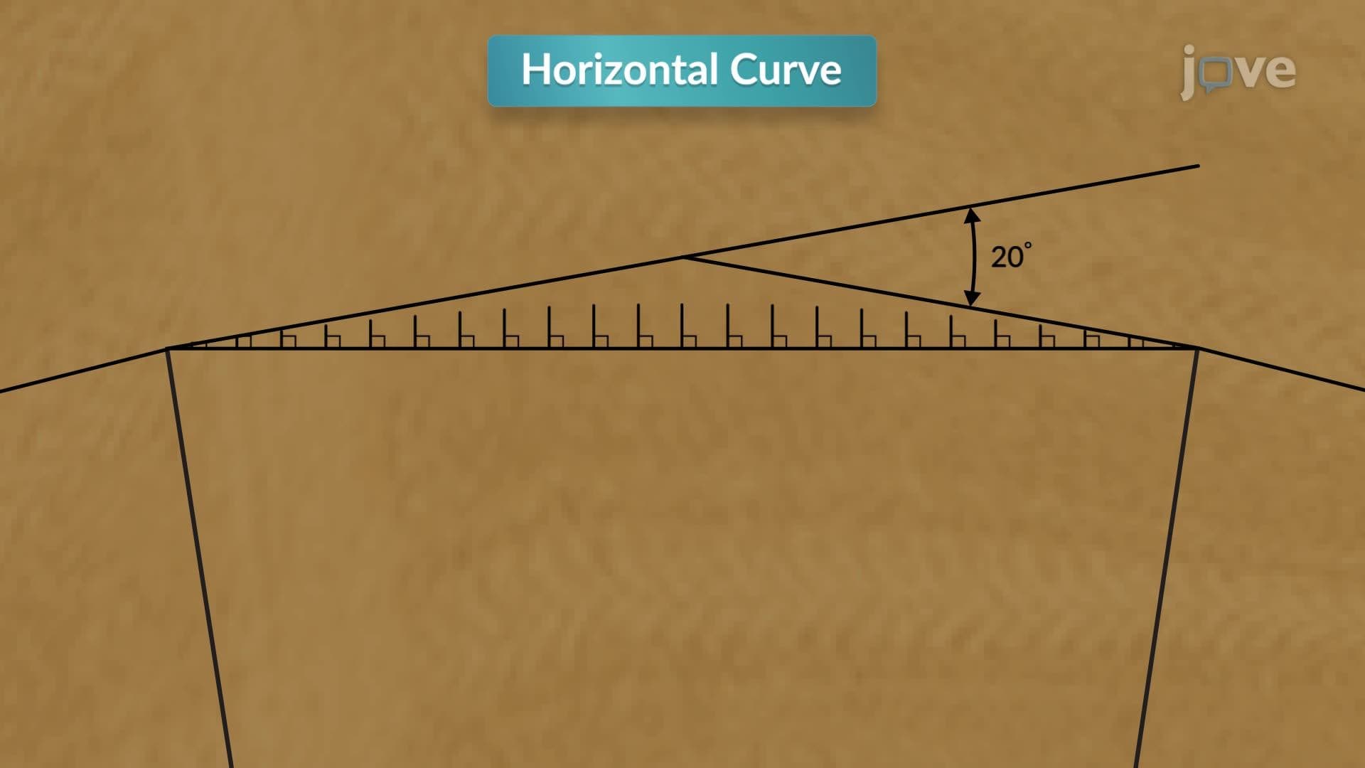
1. Horizontal Curve Fundamentals and Geometric Elements Road alignment curves connect straight highway segments called tangents through carefully designed circular arcs. The Point of Curvature (P.C.) marks where the back tangent transitions into the curve, while the Point of Tangency (P.T.) indicates where the curve returns to the forward tangent. At the Point of Intersection (P.I.), extended tangent lines meet, creating the intersection angle that determines curve sharpness. Understanding these fundamental elements enables engineers to design smooth vehicle transitions that minimize speed reduction and accident risk on major US highways like Interstate systems.
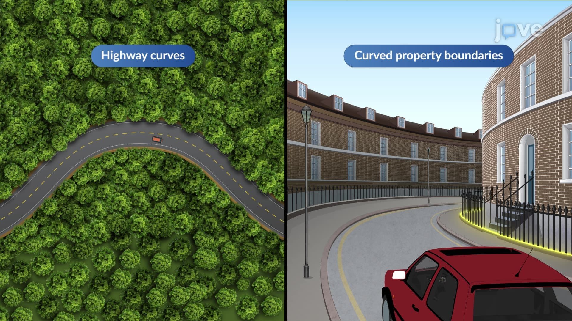
2. Degree of Curvature and Radius Relationships The sharpness of horizontal curves depends on the degree of curvature (D) and radius of curvature (R), measured using either chord basis or arc basis methods. Chord basis defines the central angle formed by a 100-foot chord, commonly used in railroad applications for gradual curves. Arc basis measures the central angle subtended by a 100-foot arc, preferred for highway design and property boundaries. Smaller radii create sharper curves requiring reduced speeds, while larger radii allow higher design speeds. These relationships directly impact safety standards established by the American Association of State Highway and Transportation Officials (AASHTO).
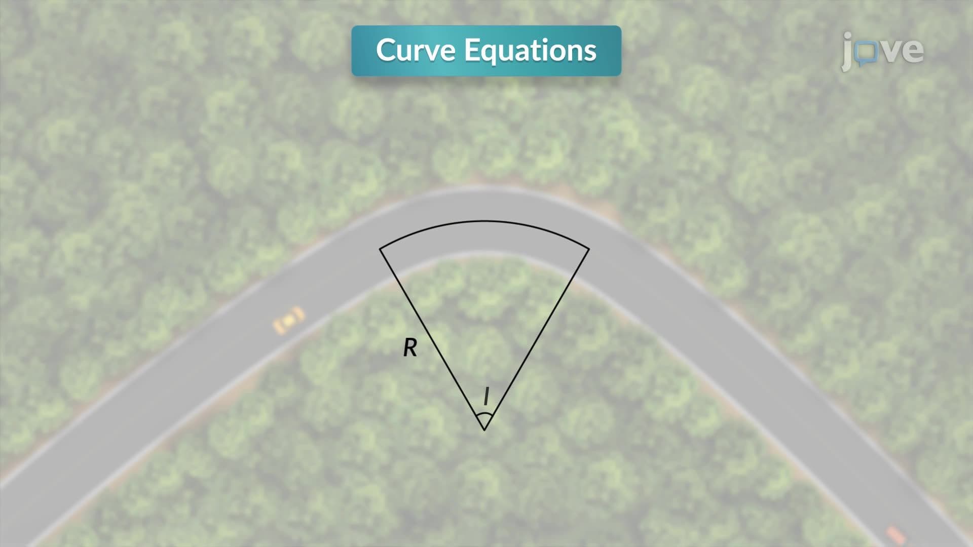
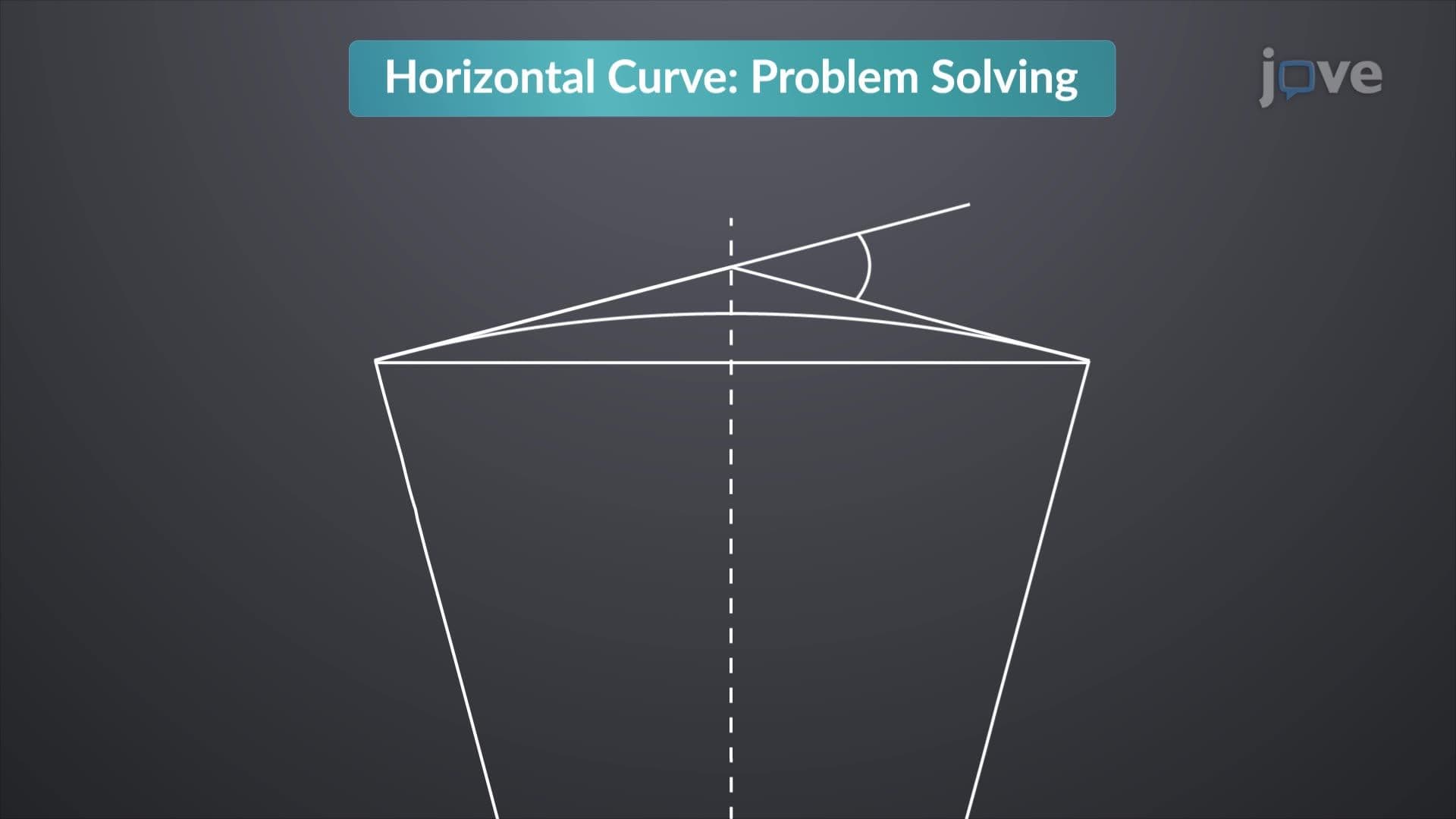
3. Curve Equations and Mathematical Calculations Essential curve equations relate geometric properties including tangent distance, chord length, middle ordinate, and total curve length. Tangent distance (T) equals R × tan(I/2), where R is radius and I is intersection angle. Chord length connects curve endpoints as a straight line, calculated using C = 2R × sin(I/2). The middle ordinate represents maximum perpendicular distance between chord and curve, found using M = R × (1 - cos(I/2)). Total curve length L = (πRI)/180 for degree measure. These fundamental relationships enable precise calculations for US highway construction projects.
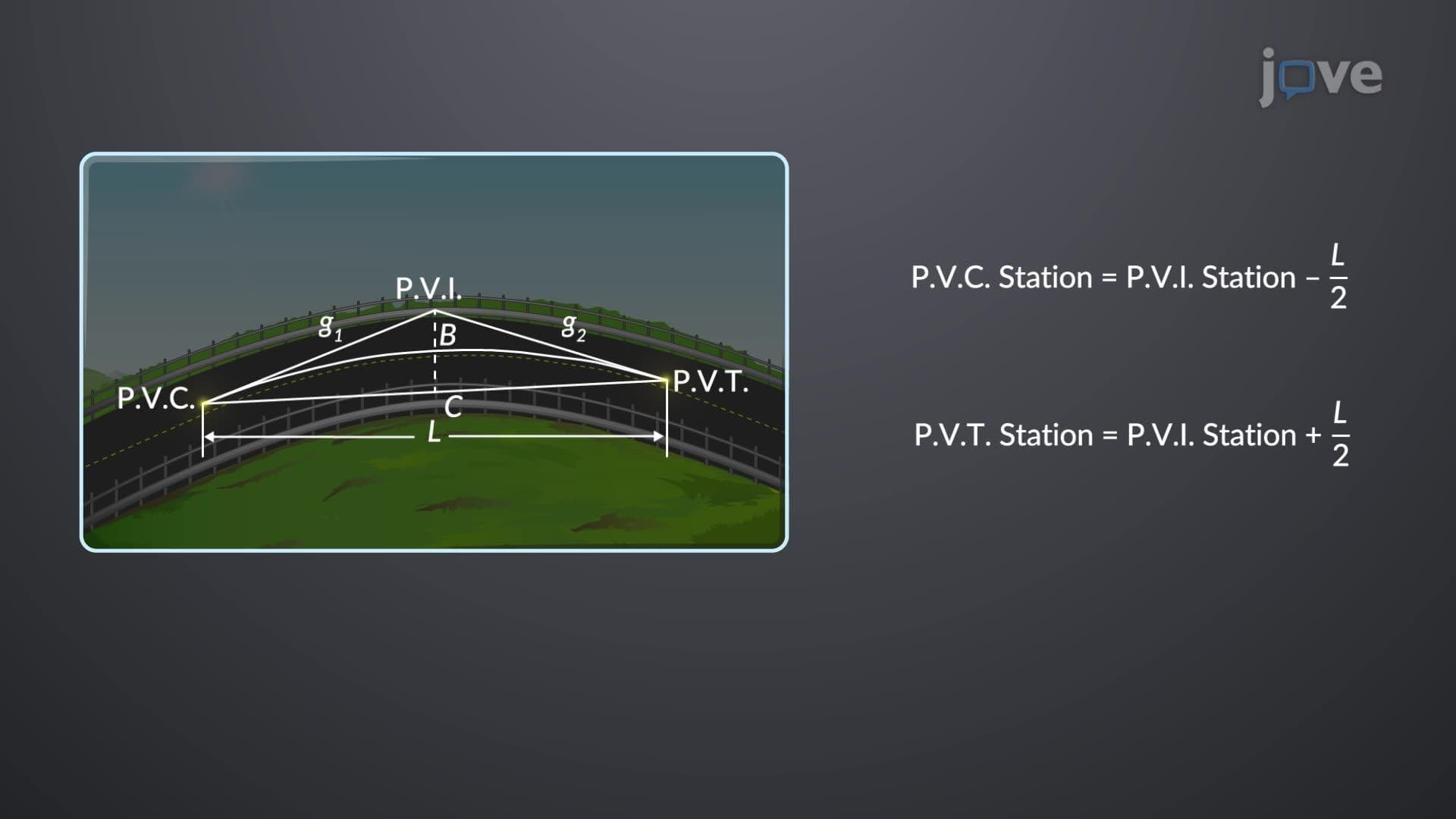
4. Vertical Curve Design and Parabolic Geometry Vertical curve road design ensures smooth transitions between different grades using parabolic geometry rather than circular arcs. The Point of Vertical Curvature (P.V.C.) begins the transition from the back tangent grade, progressing through the curve to the Point of Vertical Tangency (P.V.T.) on the forward tangent. The Point of Vertical Intersection (P.V.I.) represents where extended grade lines meet. Parabolic curves provide constant rate of grade change, essential for vehicle comfort and safety. These curves can be crest curves (connecting upward grades) or sag curves (connecting downward grades), each requiring specific design considerations for US highway standards.
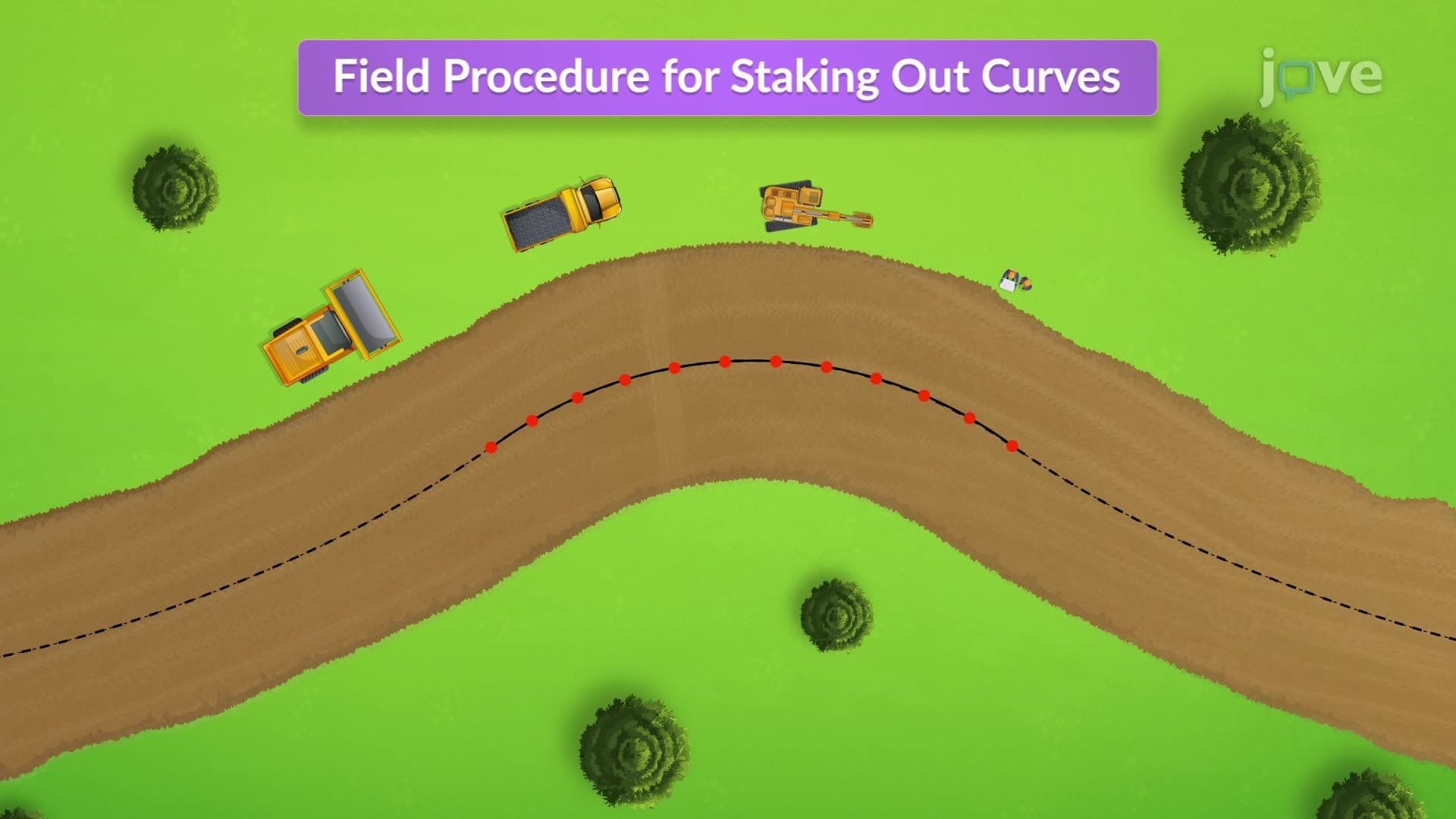
5. Field Staking Procedures and Construction Layout Accurate curve staking ensures proper highway alignment during construction using surveying instruments like total stations or theodolites. The process begins at the P.C., sighting along the back tangent and calculating deflection angles and chord lengths for stake placement. Deflection angles increase incrementally from the tangent line through the curve, with stakes placed at predetermined stations. The perpendicular offset method from long chords provides an alternative staking approach, particularly useful for simple circular curves. Proper field procedures prevent costly construction errors and ensure compliance with design specifications on major US infrastructure projects.
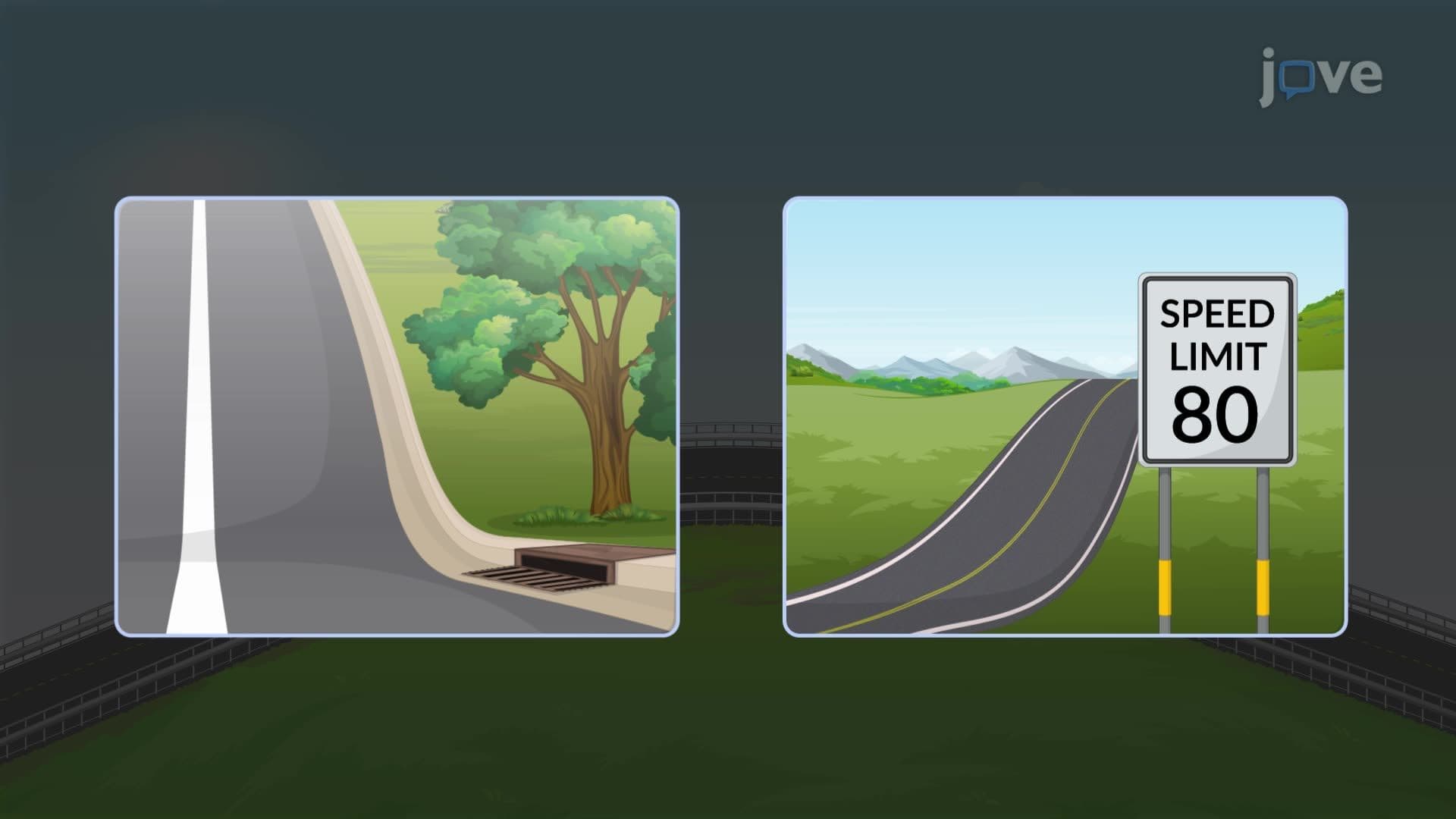
6. Sight Distance Analysis and Safety Considerations Sight distance on vertical curves determines safe stopping distances for vehicles traveling at design speeds, critical for preventing accidents on US highways. Crest curves require analysis of driver eye height (3.5 feet) and object height (2 feet) to ensure adequate visibility over hills. Sag curves depend on headlight illumination distance during nighttime driving conditions. Stopping sight distance calculations incorporate driver reaction time, vehicle braking capability, and pavement friction coefficients. AASHTO guidelines establish minimum sight distance requirements based on design speeds, ensuring drivers have sufficient time and distance to respond to hazards safely.